Arduino(TM) Projects
Dive into various aspects of Arduino.
Analog performance, particularly of Due and ATSAMD21 12 bit ADC
The
Blog for this project
Due and ARM Cortex M3
The Due is a pretty cool processor and shows what ARM Cortex 32 bit
processors have done for the market. At least some of the cost
reduction must be because instead of designing a processor
architecture from scratch, a manufacturer licenses it from ARM for a
few pennies per chip. So the manufacturer doesn't need to recoup
development costs, and the net cost to the end user is generally
lower than proprietary devices. And ARM is a good architecture. It
uses the "Thumb" instruction set optimization to minimize program
memory size. It uses caching and pipelining to increase execution
speed, and high performance peripherals with DMA to increase I/O
performance. And when you learn one ARM processor, you have learned
something about all ARMs and about all manufacturer's ARMs. With
8/16 bit bit low-end processors, there are only proprietary
architectures. With embedded 32 bits, the ARMs are winning and I
think most proprietary architectures will fade into
irrelevance. ARM Cortex M0's, the low end devices, are currently
giving the 8 bit market a run for the money.
ADC Testing
As an analog type, one of the first things I do with a new
processor is to read the analog data sheet and measure the
performance of its analog peripherals. The things I'm looking for:
- How many real bits are there (and how many "Marketing Bits")
- Gain and offset accuracy: Is calibration needed? How much?
- Can simple averaging be used to obtain more resolution?
- Can it really operate at the specified speed?
- Is the internal reference any good?
The answers to these questions tell me if the ADC is good enough
to do a certain job. Do I need to improve it? Do I need to
calibrate each system? Can I squeeze a bit more performance out of
it? Or do I need another processor or an external ADC to do the
job?
Measuring real bits
An LSB is one count of the ADC. At 5V and 10 bits, an LSB is
5V / (2^10 -1) = about 5mV. In a perfect universe you would
execute analogRead(A0) and it would return a nice stable value
equal to Vin * 1023 / 5.0. But in this universe, you get a
whole bunch of errors. The ADC has offset and gain errors, the
reference for the ADC has errors and noise, the ADC has noise, and
worst of all it has non-linearity. And the next ADC you measure,
even of the same type, will have a set of different errors.
Depending on what your accuracy requirements are, you can either
improve or correct for some of these.
Minimum industry standards dictate that an ADC has no missing
codes. Meaning that as you slowly increase the voltage, all 2^N
output values codes will eventually show up. It's a pretty low
bar. But since marketing weasels write the first page of a data
sheet, you need to dig deep into the numbers to get the whole
truth. Marketing says "12 Bits", but the engineers that design and
test these parts know the real truth, and usually publish it
somewhere on pages 2 through N.
Resolution and Accuracy
Accuracy is probably your ultimate goal. You want to know that
when you apply 1.000 volts to your 5.0V ADC you'll get 1/5 of the
full scale number. For a perfect ADC, you would get 1.00 * 1023 /
5.00 = 204.6, +/- 0.5. But to get that, you need offset and
gain accuracy of less than 1/2 LSB, a reference accurate to better
than 1/2 LSB (.05%), and an ADC with less than 1/2 LSB of INL, DNL
and noise. Even with these near perfect 1/2LSB specs,
these 6 error sources can and will all add up, and you can get
errors approaching 6 * 1/2LSB = 3LSBs. Ouch. Then if any of these
specs drift with temperature (Note* "Everything drifts with
temperature." ) then when the temperature changes, things
typically get worse. This is why an error budget is an important
part of engineering.
* Erickson's Law of Temperature Drift
Calibration
One technique to correct for some errors is to calibrate. Gain,
offset, (and reference) errors can often be calibrated out
with a simple linear correction. Higher order errors are generally
impractical to compensate for. Remember the equation of a line
from high school: Y=MX+B? If you know M, the gain
correction, and B, the offset correction of your ADC, then you can
correct for these. If you know M and B at various temperatures,
you could even compensate for temperature drift but setting
temperature and building a table of calibration vs. temperature is
usually too expensive. INL, DNL and noise are harder to compensate
for. INL requires that you know the errors at every possible input
value and build a table of corrections. It can be done, but again,
expensive (time consuming) and uses lots of memory. Few real
systems go to this level of complexity. Engineers usually just buy
a better ADC and reference. It is the rare ADC that has gain and
offset error specs as low as1/2 LSB.
In the good-old-days, trim-pots were used to correct for offset
and gain errors and to provide calibration. But trim-pots require
manual labor to adjust and are prone to their own thermal and
mechanical drifts. Good trim-pots are fairly expensive. A 10 turn
trim-pot costs about the same as an Arduino processor chip, thank
you, Gordon Moore. When writable non-volatile memory such as
EEPROM became widely available, trim-pots for calibration became
rare. In the case of most Arduinos, calibration factors can
be stored in either EEPROM or Flash program memory. If you don't
mind re-calibrating every time you power up, store them in RAM.
That requires one or more precision sources that can be measured.
This is how modern digital oscilloscopes and waveform generators
do it.
So what are the real error numbers?
ADC Voltage Reference
Most Arduinos default to using VCC as the ADC reference. If the
VCC is 5V, then it either comes from the USB connector or from the
voltage regulator. USB 5V as a reference is pretty bad, since it
comes from a PC with about 3-5% basic accuracy. Then there are
voltage and ground drops across the cable, depending on the host,
the length of the USB cable, the other devices plugged into USB,
and the USB current load. Even turning on a handful of LEDs
on your Arduino can vary the supply voltage. Forget about powering
1/2 Amp of relays, servos or motors.
But.... there is one case where using a crappy reference works.
That is the case where the sensor is ratiometric and is powered
from the reference. When the reference voltage drops, the ADC gain
increases. As long as the sensor output also drops, the reference
errors cancel out. Examples of ratiometric sensors are thermistors
and other resistive sensors with a pull-up resistor, and bridge
sensors (pressure and strain).
Adding a more precise voltage reference to an Arduino isn't hard.
Pay a few dollars, and connect a 2 to 4.5V (3.3V max on the Due)
reference source to the reference pin, and set the Arduino to use
external reference with analogReference(type). Compared to VCC,
this will provide better accuracy, noise, and stability.
The Due and some other 3.3V Arduinos use the 3.3V power supply
for a reference. It can still be noisy and have a few percent of
error, but is better than USB +5V since it is locally regulated.
What is the difference between a reference and a linear voltage
regulator? The big difference is that a reference is always
specified for temperature drift but a linear regulator generally
is not. A linear regulator is basically a high power, not too
accurate reference. Good references are also better than 1%,
specified for noise, low power, etc.
Measuring ADC noise
ADC noise is one limit of ADC accuracy. All you need for a quick
ADC measurement is an example program that measures the ADC
outputs the data to a serial port. The Arduino Example
"AnalogReadSerial" does this nicely. The steps are simple:
- Apply any known voltage to an ADC channel.
- Run the program AnalogReadSerial.
- Run the Serial Monitor and view the ADC values, one per line
- Grab a bunch of values with your mouse. A few hundred readings
will do.
- Copy and paste them into Excel or another spreadsheet.
- Use Excel to plot the data.
- Use Excel to calculate min(), max(), stdev() and average()of
the data.
- The peak-to-peak noise is max() - min().
- The RMS noise is the same as the standard deviation, assuming
a constant DC input and a roughly Gaussian distribution. Noise
usually is.
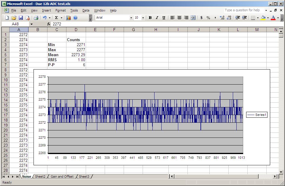
Here is the noise plot and measurements for a Due 12 bit (4096
count) ADC. I measure 6 counts p-p and 1.00 counts RMS noise. For
a Gaussian response, the ratio of p-p to RMS is about 5 to 1.
Notice int the test data that there is only one point at value
2277. Without that sample the p-p would be 5, not 6.
1.00 counts of ADC noise basically takes 1 bit away from the
specified ("Marketing") 12 bits, making it an 11 bit ADC. Look a
the SAM3S
processor ADC specs and you will see that the ENOB
(equivalent Number of Bits) is INL (Integral Non-Linearity)
spec is +/- 1.2LSB max. over full temperature. (Equivalent number
of Bits) is 10 typ. 11 max. ENOB is a measure of AC (dynamic)
accuracy, not DC noise.
Also look for any repeating pulses or patterns in the noise data.
These artifacts generally indicate some periodic noise or
interference pattern. You should dig in with a 'scope to see what is
causing it.
Another good noise analysis tool is the histogram. By displaying
a histogram of the noise readings, you can see if the distribution
is roughly gaussian or has some other distribution.
Increasing Resolution with Averaging
If the ADC noise is gaussian and is 1/2 LSB or more, then you
can use this to your advantage by averaging the ADC values. Noise
decreases by 1/(N^2). So averaging 4 values reduces noise by 1/2,
providing another bit of resolution. Averaging 64 values
improves noise by 1/8, providing nearly 3 extra bits of resolution.
This method is particularly useful when you measure DC or
slowly varying readings such as temperature. Summing N readings with
integer math is easy. Then divide the sum by the number of samples
collected. The easy way is to do a floating point divide which will
produce a floating point result with the fractional part indicating
fractions of an ADC LSB.
On 10 bit Arduino ADCs, the noise is typically less than 1/2 LSB and
the distribution is typically not Gaussian. So averaging does not
work. And don't forget that additional resolution is no additional
accuracy. Ultimate accuracy of the ADC is dependent on INL. The INL
spec for the Due are +/- 1.2LSBs over the full temperature range.
I'd guess you would get about +/- .75 LSB over a narrow room
temperature range. Its just a guess.
Measuring and correcting Gain and Offset errors
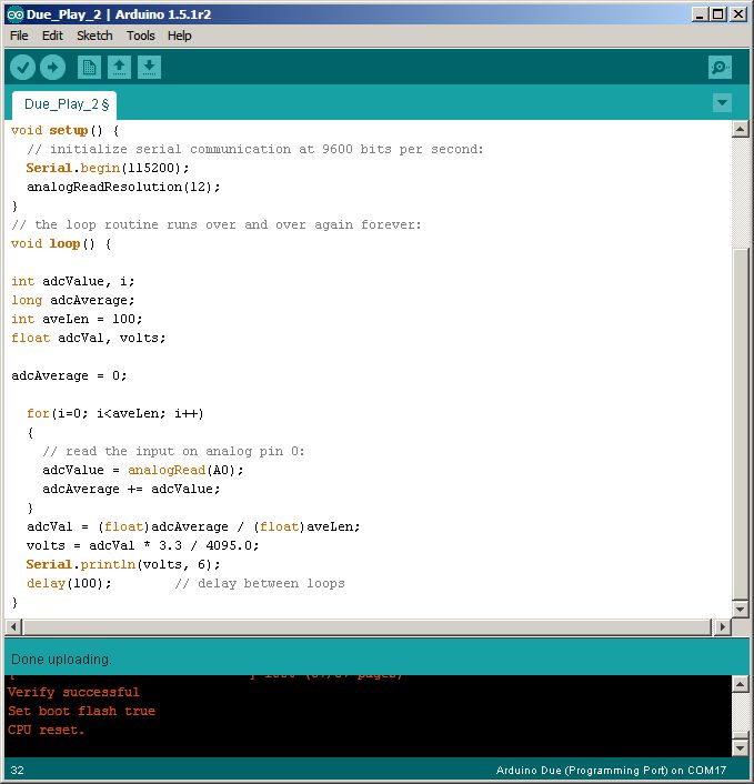
Write a program to read and average 100 ADC readings, scale the data
from Counts to Volts, and output the average value in floating point
format, say 5 digits. Here is
the program for a Due, with 12 bits of ADC resolution.
Then apply a few known voltages spread out over the ADC input range.
Use a multimeter with more resolution than your ADC to measure the
voltages. Record the applied voltages and the measured voltages.
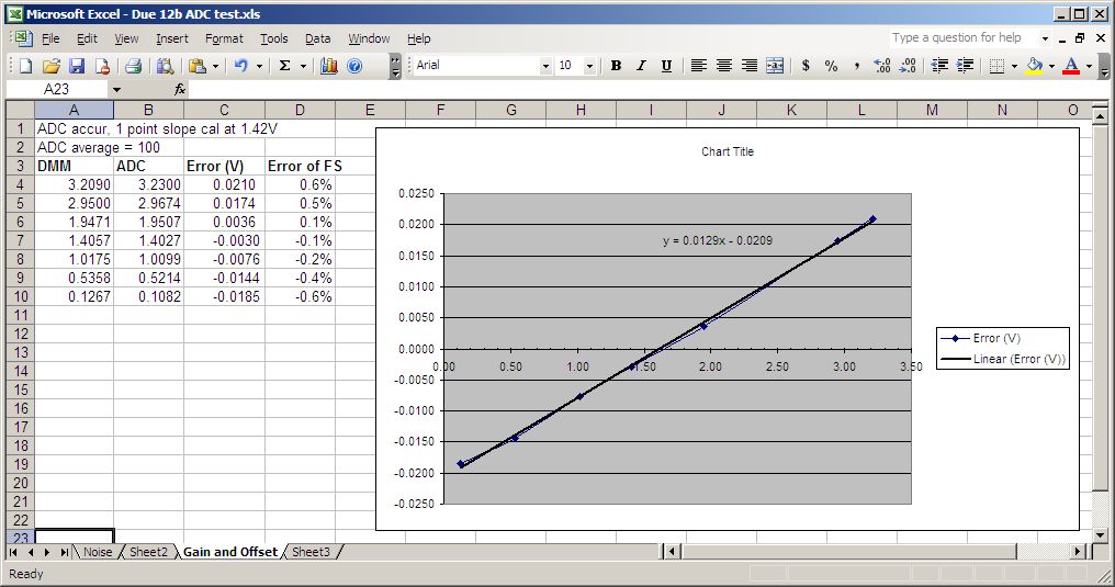
Enter the numbers into 2 columns in Excel. Plot the measured
voltages vs. the known voltages. That plot will give you the gain
and offset errors. I like to just plot the errors: measured value
minus the expected value (Vin * 1023/ 5.0). You can use
Excel's trendline feature (right click on the plot) and a linear
regression to calculate your gain and offset calibration values.
Then display the trend line equation on the plot. You may need to
display more digits for the M (slope) and B (intercept).
This is the 12 bit ADC on a Due board, with the default +3.3V
reference. It has -20.9mV of offset error and +1.29 % gain error.
To correct for this, add 20.9mV to your measurement and multiply
by 1 / 1.0129.
The gain and offset specs for the Due ADC are gain error of
typically 0.56% and offset of 11.5 codes (9.2mV). This part had
20.9mV or more than 2x the typical offset, and 12.% or more than
2X the gain error. Don't trust typical specs.
The down-side to gain calibration is that you introduce missing
codes. By multiplying the ADC counts by a non-integer number, some
codes disappear, causing some 2 code jumps in your readings.
Averaging first means that you have a bit more resolution than one
LSB, and the jumps are obscured.
Due ADC Speed
The function analogRead() in a tight loop takes 39uS per
loop. Considering that the ADC can convert in 1uS and the processor
can execute dozens of instruction in 1 uS. what's the beef? I dug
into the analogRead() function to find out why. The first
observation is that analogRead() does not initialize the ADC, it
just sets the channel, starts a conversion and waits for the result.
Initialization is done elsewhere. So basic code structure isn't the
problem. Then I dug into the register settings. The register ADC_MR
(Mode Register) contains a number of settings that affect ADC
timing: TRACKTIM, SETTLING, STARTUP, and PRESCALE in addition to
SLEEP. The following code allow you to display the 32 bit contents
of the MR register via the serial port.
unsigned long reg;
reg = REG_ADC_MR;
Serial.print("REG_ADC_MR = ");
Serial.println(reg, HEX);
When run, you get:
REG_ADC_MR = 103C0100
The master clock, MCLK is 84MHz. The ADC prescaler is set to 0x01
which is divide by 4 so the ADC clock is 84MHz / 4 = 21MHz. That is
as fast as it can go, so that's not the problem. The ADC clock
period is 1 / 21MHz = 37.6nS. The 0xC sets STARTUP is 768. 768 /
21MHz = 36.6uS. Bingo! So I set STARTUP to a smaller number, 2,
(value = 16 / 21M = .76uS) with this line of code:
REG_ADC_MR = (REG_ADC_MR & 0xFFF0FFFF) | 0x00020000;
And the ADC loop now takes 4uS. Cool. To make it even faster, I also
set the Settling number down from 3 to 1. The data sheet recommends
settling and tracking numbers. It also says that if you want the ADC
to convert faster than 500KHz, set the IBCTL field in ADC_ACR to
01. I checked, and it was already is set to 01.
I found the Arduino line of code that initializes the ADC in
\arduino-1.5.1r2\hardware\arduino\sam\variants\arduino_due_x\variants.cpp
adc_init(ADC, SystemCoreClock, ADC_FREQ_MAX, ADC_STARTUP_FAST);
Sure, it's a hack to use hex numbers to set register fields, but
until I find all the right .h files, it will do. Here are the
#defines for the STARTUP field from
\arduino\sam\system\libsam\include\adc.h
/* The normal adc startup time*/
#define
ADC_STARTUP_NORM 40
/* The fast adc startup
time*/
#define
ADC_STARTUP_FAST 12
This may be a bug. STARTUP is a four bit field so 12 (0xC) works,
but 40 (0x28) won't work. And 12 sets the value to 768 which is why
the ADC is so slow. So I suspect that the programmer confused the
value with the hardware settings. The table of values vs. register
settings is in the SAM3S processor
manual.
Accessing Due Registers
I was unable to find a document showing how to directly access
Due registers, but by doing text searches in the Arduino
directories, I found that all of the SAM3X registers are defined
simply as the register names preceded by REG_ such
as REG_ADC_MR. Don't forget that
these registers are generally 32 bits, so use unsigned long
variables to read and write them.
Measurement of ATSAMD21 ADC (Mar
2024)
In 2023/2024 I was looking for a small module processor with a
low-ish cost and decent 12b performance. My favorite Teensy
processors have all dried up except for Teensy 4. I can't see using
a 600MHz processor in places where an 8 bit ATMEGA would easily do
the job. But a 48MHz ARM M0 for $12 would be nice. I wanted a
reputable supplier and good Arduino support. I bought 2 ATSAMD21
modules from Adafruit, the ItsyBitsy M0 Express ($12) and the
Feather M0 Express. These have 12b ADCs and specify INL of about
1.4LSB typical, 4.5LSB max. Noise is 1mV RMS. Not too bad for an
on-chip ADC.
I tested the ADCs with my precision 18b DAC. I wrote a function to
calculate the RMS noise (using standard deviation) of an array of
readings. I measured the noise with different averaging values from
1 to 1000.
The ADC is set to 12 bits using analogReadResolution(12).
Conversions in an averaging loop take about 28uS at 12b using
analogRead(). Averaging 100
samples takes 2.8mS.
Peak-to-peak noise is about 5x the RMS values. So if you don't want
your LSBs to bobble, more averaging.
| Averages |
Noise RMS, mV
|
ENOB
(bits) |
1
|
3.0 mV
|
10
|
10
|
1.0 mV
|
11.5
|
100
|
0.4 mV
|
12.5
|
1000
|
0.0015 mV
|
13
|
Got anything better??
For basic measurements, 10bits is decent, and 12b is better, if you
can average. If you need better than 12 bits, the ADS1115 is a nice
4 channel, 16 bit part for $5. Cheap eval boards are available. It
can do ADCs from +/- .256V to +/- 2.5V, single -ended (4 channels)
or differential (3 channels. I2C, supports up to 4 devices on I2C.,
and in a VSSOP-10 package. Convert times are 8 to 860 SPS. Good for
DC and low frequency signals.
I2C is pretty easy to isolate using parts like the Siliconix
SI860x or TI ISO154x.
If yo need faster ADCs. there are sampling SPI ADCs at 12 to 16
bits.
Of course there are plenty of 20 and 24 bit ADCs.
Back to Dave's Home Page
This page was last updated 3/3/2024