Encoders,
Interrupts and I/O expansion with Arduino
My approach to reading
front-panel controls, including encoders
The problem
Reading buttons and other
user inputs in the loop() code of an Arduino is generally a bad
idea. Other routines can block this code from executing.
Particularly updating displays which can take many 10's or even
100's of mS. A quick button press can occur in 20-50 mS, and
can be missed.
Mechanical switches, including encoders, generate 'contact
bounce'. Contact bounce occurs when a switch is turned on or off.
It causes multiple, fast pulses for about 1 to 10mS. And it gets
worse as the switch ages, and its contacts wear out and oxidize.
The Arduino libraries for encoders and switches are either polled,
or interrupt based. Either of these is not ideal.
Polling can miss events because of long events in the loop().
Interrupts work better, but the 1-10 mS of contact bounce can
cause many interrupts to occur. And each switch requires a
separate I/O pin with interrupt capability. This is a problem with
5, 10 or more switches. Filtering the encoder with pull-up
resistors and capacitors to GND reduces the contact bounce.
Some warnings
When I worked at
Analogic, we had a product called the AN8200, a precision voltage
source. We referred to it as the VoltBox. It had 6 encoders, and
each controlled one digit on the front panel. These were
old-school Grayhill mechanical encoders. They worked well when
new, but as they got old and the contacts oxidized, the contact
bounce increased, and the switches caused erroneous results. The
engineers who wrote the firmware that reads the encoders didn't
take this into account. The encoders, no longer available,
need to be painfully removed, disassembled, contacts cleaned,
assembled, and reinstalled.
HP generally uses quality components. But their modern instruments
such as the HP 33250A and 33220A waveform generators have
notoriously unreliable encoders. There are a number of Youtubes on
this issue.
Scope of the
discussion: not position encoders
This page relates to
optical and mechanical encoders intended for front-panel controls.
Other encoders used for position control are typically higher
resolution and are optical. These can have much higher resolution
and speed, and should be designed to never miss a pulse. I
recommend using specific hardware readers for these. There are
specific ICs, and there are microprocessors with encoder reading
hardware. Use one of these solutions. Unless the encoders are slow
(< 1KHz), software solutions will cause you headaches.
The solution
Most embedded
applications have some real-time requirements, including any with
buttons or encoders. I use a timed interrupt, generally about 1mS,
to read all of the front panel switches and other critical I/O
requirements. For example, if I need a regular ADC measurement, I
put it in the 1mS interrupt handler. If the event can occur at a
slower rate, a simple counter in the interrupt routine can
generate slower interrupts.
Timed Interrupts
With a timed interrupt,
be careful not to include any lengthy code. Try to avoid while()
loops, or lengthy for() loops. In-line code, including digital and
analog I/O is pretty safe. I generally use a spare digital output
bit to see how much time the interrupt routine takes: set the I/O
bit at the beginning of the interrupt and clear it at the end.
With a 'scope, you can easily see how long the interrupt is
taking.
Another gotcha with interrupts is sharing I/O resources. If loop()
is using an I/O resource (a Pin, ADC, SPI, I2C, etc.), then the
interrupt trying to use the same resource can mess it up big-time
unless some type of semaphore is used to avoid conflicts. It can
get tricky. And you really don't want your interrupt routine to be
waiting a significant time for a slow I/O device in loop(). Be
very careful..... Try to have each resource be either polled in
loop() or using an interrupt, but not both.
In the early days of Arduino, I struggled with timed
interrupts, since each type of processor used a different timer. I
would read the processor data sheet and bang the appropriate
registers. Now there are timed interrupt libraries that are
consistent across platforms. I use https://github.com/khoih-prog/SAMD_TimerInterrupt
for the ItsyBitsy SAMD21. He has others for other processors.
Encoders
Mechanical encoders are
low-cost and convenient ways to control digital stuff on a
front-panel. They are basically switches that operate much faster
than simple push-buttons. Most have two outputs, A and B, that
operate in quadrature. There are many encoder options:
- Quadrature or
absolute
- Mechanical detent
(click) or no click
- 10-20 or more clicks
or pulses per rotation (PPR)
- 1 or 4 transitions
per click
- Mechanical
(switches) or Optical
- Optional push switch
- Various sizes,
shapes, and pinouts
- Various mountings,
shaft lengths, and shaft types.
- Knob size:
- Larger knobs are
easier to control with precision
- Smaller ones can
be controlled faster
A simple Digikey search
for encoders shows about 10,000 part numbers. An
embarrassment of riches. I generally use these ones from TT.
- EN11-HNM1AF15
20PPR, no switch, short 'D' shaft, $2.15
- EN11-HSM1AF15
same, with a push switch, $3.00
Quadrature means that the
2 outputs are 90 degrees out of phase with each other. When you
rotate in one direction, first switch A closes, then A and B, then
B, then both OFF. In the other direction, B is first. By looking
at the phase of A vs B (which comes first), the direction of
rotation can be determined.
Most mechanical ones have a click and are 16 to 24 clicks per
rotation. Most are also 4 transitions per click.
Optical ones may or may not have a click, can have many more
pulses per rotation, and generally don't have contact bounce. With
a lot of pulses, the knob size should also be increased.
How to read an encoder
The standard Arduino
libraries for encoders are either polled or interrupt driven.
Instead, I wrote my own code, using a 1mS timed interrupt:
- Read the A and B
bits every 1mS
- Combine the 2 bits
with the previous reading's 2 bits into a 4 bit value
- Use a look-up-table
(LUT) to output:
- Idle: no change
- Up count
- Down count
Here is the
Look-up-table (encoder_logic) for a TT encoder and the the
Interrupt code.
/* Encoder */
/* For encoders that generate 4 transitions per click such as most mechanical encoders.
Note that mechanical encoders need pull up resistors and should also have R-C filters
*/
const uint8_t encoder_logic[] = {
/*old new action
---------------------- */
/* 00 00 */ NADA,
/* 00 01 */ NADA,
/* 00 10 */ DECR,
/* 00 11 */ NADA,
/* 01 00 */ NADA,
/* 01 01 */ NADA,
/* 01 10 */ NADA,
/* 01 11 */ NADA,
/* 10 00 */ INCR,
/* 10 01 */ NADA,
/* 10 10 */ NADA,
/* 10 11 */ NADA,
/* 11 00 */ NADA,
/* 11 01 */ NADA,
/* 11 10 */ NADA,
/* 11 11 */ NADA
};
/* getEncoder()
This is the interrupt routine for the encoder.
The encoder is an optical encoder knob that outputs A-B quadrature signals. The knob is
rotated relatively slowly, so once every 1 mS the 2 bits are polled. These are compared
to the previous readings and depending on the sequence, either the count value is
incremented, decremented or not action (NADA).
The logic is contained in encoder_logic[] a table.
The encoder state is 4 bits. The 2 LSBs are the new bits. The MSBs [3:2] are the previous readings.
*/
void getEncoder(void)
{
uint8_t action;
static uint8_t encoder_state;
/* read 2 LSBs, shift up the previous bits */
encoder_state = (encoder_state << 2) | (digitalRead(ENCB) << 1) | digitalRead(ENCA);
action = encoder_logic[encoder_state & 0x0F]; /* Look up action: 4 LSBs only */
if (action == INCR)
encoder_count++;
if (action == DECR)
encoder_count--;
}
Reading Keys (buttons)
There are a million ways
to read buttons. Since I'm already using a 1mS interrupt, it is
fairly fast to scan all the buttons, and debounce. And while you
are at it, you can time the key press for key repeat, long press,
etc.
I keep one variable keyState per button to maintain the key state.
keyState = 0 means it is not pressed. Then count every scan that
the button is pressed. If it bounces, reset to 0. After about 10
mS, generate a key valid for that key.
I/O Expansion
When you have a bunch of
buttons and an encoder on a front panel, you can run out of I/O
pretty quickly. The Nano type processors (Nano, Teensy, ItsyBitsy,
Feather, ESP32...) have about 10 or 15 general purpose digital
I/Os other than I2C, SPI and Serial. An encoder with a press
button uses 3 I/Os, and switches use one each. LEDs use one each
also.
I like to read and debounce all the buttons in a timed interrupt.
So reading all the bits should be fast. Here are several ways to
expand I/O
Use a multiplexer
An analog or digital
multiplexer can read several switches and allow fewer bits to
handle them. Analog switches have the advantage that the
processor's pull-up resistor is also multiplexed. Digital muxes
require one pull-up resistor per switch.
Multiplexer
|
#
of switches
|
Output
Bits
|
Input
bits
|
Notes
|
Cost
|
8:1
analog (74HC4051)
8:1 digital (74HC151)
|
8
|
3
|
1
|
Requires
3x8 digital writes.
Output pins can be shared if > 8
Digital requires pull-up per switch
|
$0.30
|
16:1
analog (2x 74HC4051)
|
16
|
4
|
1
|
Requires
4x16 digital writes
|
$0.60
|
Use a crosspoint
(matrix)
An X-Y matrix of
switches can be used. For a large number of switches this is
practical. For 16 switches, this requires 4 output and 4 input
bits, so only a 16 -> 8 pinout savings. If a HW 2:4 decoder
is used, then that saves 2 more output pins, so a 16 -> 6
savings. .
For 8x4 with a 3:8
decoder, 3 output and 4 inputs are needed for a 32 -> 7 pin
savings.
analog or digital
multiplexer can read several switches and allow fewer bits to
handle them. Analog switches have the advantage that the
processor's pull-up resistor is alo multiplexed. Digital muxes
require one pull-up resistor per switch.
In a martix, there is an
artifact called 'shadowing'. This is when 2 buttons are pressed at
the same time, and the processor cannot tell that all 4 of the
keys that share the same rows and columns are not pressed.
And if the outputs are totem-pole (High and low drive) then
pressing multiple buttons can short two or more outputs, causing
high current. Using a diode on each output or using open-collector
(or open-drain) outputs addresses this issue. In Arduino, outputs
can be open-drain, but that requires additional port operations.
For a 4 x 4 matrix with HW decoder, each column requires 2 writes.
Each row requires 4 reads. So 4 * (2 + 4) = 24 operations.
For a 8 x 4 matrix with HW decoder, each column requires 3 writes.
Each row requires 4 reads. So 8 * (3 + 4) = 72 operations.
Since Arduino I/O uses one bit reads and writes, this can be slow.
Using a DigitalReadFast and DigitalWriteFast library will
help. If a bunch of bits are in the same processor I/O port,
low-level register reads would speed it up a whole lot. Maybe
there is a library for this?
Another speedup is to read only one or 2 columns per 1mS
interrupt. 2ms or 4ms poll time for buttons ain't bad.
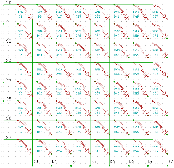
By adding a diode per-switch, full isolation can be achieved:
there is no shadowing, and multiple keys can be pressed and
correctly detected simultaneously. The diodes can be dual diodes
in SOT23 or some type of quad diodes. Here is a circuit I borrowed
from EEVBLOG.
In this circuit, the columns D[7:0] could be driven by a 3:8
decoder such as 74HC138 to save 5 more pins. The S[7:0] pins need
pull-ups.

BTW, an encoder or multiple encoders can be wired into this type
of matrix and can be read as just 2 more switches. An encoder is
simply 2 switches with a common pin.
Use I2C or SPI
Expanders
There are many 8 bit
and 16 bit I/O expanders. These allow the SPI or I2C
busses to access many switches, LEDs, etc. SPI at 4MHz is
generally much faster than I2C at 400KHz. These have the
added advantage of using much fewer wires to the front panel.
SPI can be bit-banged or use HW SPI.
As I mention above, SPI
and I2C devices that are controlled during interrupts need care
if shared with loop().
The MCP23017 is a I2C,
16 bit expander. At 400KHz, the 16 bits can be read in about 30
bit times (2.5uS) or ~77uS. $1.70. Not bad. But 80uS every 1mS
is 8% of the CPU processing power, just to read 16 switches. It
comes in a DIP for prototyping, SSOP, and an easy-to-solder but
large 28SOIC. There are weak pull-ups (100K) for switches.
MCP23008 is 8 bits.
MCP23S008 and 23S017 are SPI versions. Bit-Bang SPI is about 10x
faster than I2C.
There are I2C matrix
keypad expanders also available if many switches are needed. I'm
not familiar with these. Do they have proper anti-shadowing, N
key rollover, etc.? Most are QFN or BGA packages.
DIY SPI Expanders
This is a good approach
for high bit count mixed Input and Outputs.
The 74HC594 and others
are 8 bit output ports that can be wired to SPI. They can be
cascaded to add many more outputs. $.65. The 'HC595 is similar,
but has tri-state output OE/, and has no output reset. $.30. If
you need the outputs to be reset, use the '594.
For inputs, the 74HC165
will connect to SPI. The SH/LDn pin is asynchronous. The '166
has synchronous load. $.30.
The MISO pin needs a tri-state if it is shared with other SPI
devices. The SPI CS/ needs to be inverted with the '165. With
the '166 CS/ can be used directly, but it's synchronous, so a
SCK is needed.
There are many 8 bit
and 16 bit I/O expanders. These allow the SPI or I2C busses to
access many switches, LEDs, etc. SPI at 4MHz is
generally much faster than I2C at 400KHz. These have the
added advantage of using much fewer wires to the front panel.
The MCP34017 is a I2C
16 bit expander. At 400KHz, the 16 bits can be read in about 30
bit times or ~80uS.
CharliePlexing
Charlieplexing is when
you minimize I/Os for multiplexing LEDs or switches. LEDs lend
them selves to this nicely because they have built in diodes.
And just one resistor per pin.
Switches require a
diode per switch.
Analog keypads
My Whole House
(Multizone) audio system uses remote, wired, keypads in several
rooms. These are analog keypads, read by the processor ADC. Each
keypad uses up to 8 buttons each. Each uses one ADC pin. The
buttons select 0 to 7, 1K resistors in series. There is a 4.7K
pull-up on each ADC pin. So the ADC reads the resistance of the
keypad, quantizes it to the nearest 1K value, and de-bounces it.
The keypads are simple,
and only need 2 wires. GND and SIGNAL. Since they can be ~50
feet of twisted-pair wire away, I also use 1K resistors in
series with each for EMC, ESD, etc. So the actual resistance
measured is 1K to 8K.
This technique can be
used locally as well. 2 wires to the keypad, one resistor per
switch. One ADC input. Easy-peasy.
I wrote this in STM32
code, not Arduino. It works well with good debouncing and
decent quaality switches. The only problem I had is that one of
the keypad boxes is outdoors. Every year or 2, I'd have to
replace or clean the buttons. I finally found some cheap / good
waterproof buttons on Amazon.
Analog Encoder
Can a similar trick be
used to read an encoder? I wired 1K and 2K resistors across the
A and B contacts of an encoder, and used a 5K (4.99K) pull-up.
You need to detect 2 switches, so the switch resistors should be
binary values. I use 1K and 2K.
- With both A and B
OFF: 3K
- With A ON: 2K
- With B ON 1K
- With both ON 0K
Here is the code. I'm
still deciding if this is how I want to go.
/* Reads analog encoder. A has 1.0K, B has 2.0K, pull-up is 5K, cap is .1uF
Works with encoders that are 4 states per click: TT or bourns
OFF - A - Both - B 0-1-2-3
OFF - B - Both - A 0-3-2-1
Idle, 0, both OFF : 3K / (5K + 3K) = 3/8 * 1023 = 383
A, 1 ON : 2K / (5K + 2K) = 2/7 * 1023 = 299
B, 3 ON : 1K / (5K + 1K) = 1/6 * 1023 = 170
Both ON, 2 : 0K / 5K + 0K) = 0/5 * 1023 = 0
Tolerance of +/- 30 counts seems to work well.
Reads ADC once, checks against limits, assigns state.
Then encCount detects transitions from Both to A (increment)
or Both to B (decrement).
To change direction, change encCount ++ to -- and vice versa
*/
void readEncoder(void){
#define EO 383
#define EA 299
#define EB 170
#define EAB 0
static char encSt, encStD1, encStD2; // idle. 1:A, 2:BOTH, 3: B
#define tol 30 // +/- Tolerance (range for valid encoder ADC values
int encAn1 = analogRead(0);
int encAn = analogRead(0);
if ((encAn - encAn1) < 20 && (encAn1 - encAn) < 20){ // Read twice for stable V
if (encAn > (EO-tol) && encAn < (EO+tol)) { // Idle
encSt = 0;
}
if (encAn > (EA-tol) && encAn < (EA+tol)) { // A
encSt = 1;
}
if (encAn > (EB-tol) && encAn < (EB+tol)) { // B
encSt = 3;
}
if (encAn < (EAB+tol)) { // Both
encSt = 2;
}
if (encStD1 == 2 && encSt == 1) { // Transition BOTH to A
encCount --;
// Serial.print( "encCount = "); Serial.println( encCount);
}
if (encStD1 == 2 && encSt == 3) {
encCount++;
// Serial.print( "encCount = "); Serial.println( encCount);
}
encStD2 = encStD1;
encStD1 = encSt;
}
}
It works pretty well,
but not completely reliable. I decided this isn't a great
idea since it only saves one I/O pin. Instead, I'll use a
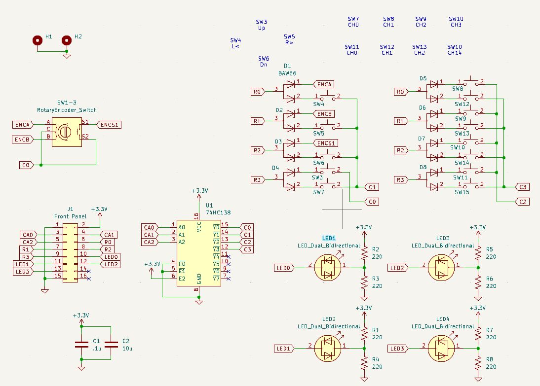
keyboard matrix with diodes. The encoder is just 2 more switches
in the matrix. Here is the schematic for the front panel
board for the Quad-SMU project. Because the Encoder can have its
two switches closed at the same time, diodes are needed on it.
The other diodes are just to allow multiple simultaneous button
presses to be detected. It has:
- One Encoder with
switch
- 13 momentary
switches
- Switches matrixed
with one diode per switch.
- 74HC138 2:4 decoder
to save 2 I/O pins
- 4 bi-directional
GN/RED LEDs
- 16 pin connector to
CPU board

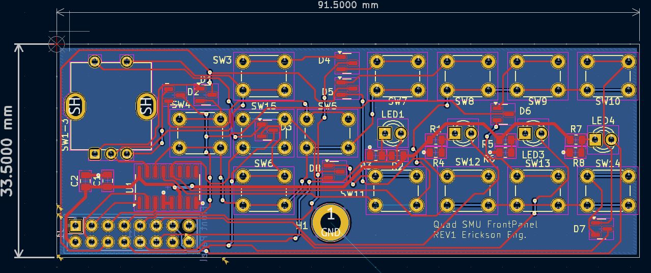
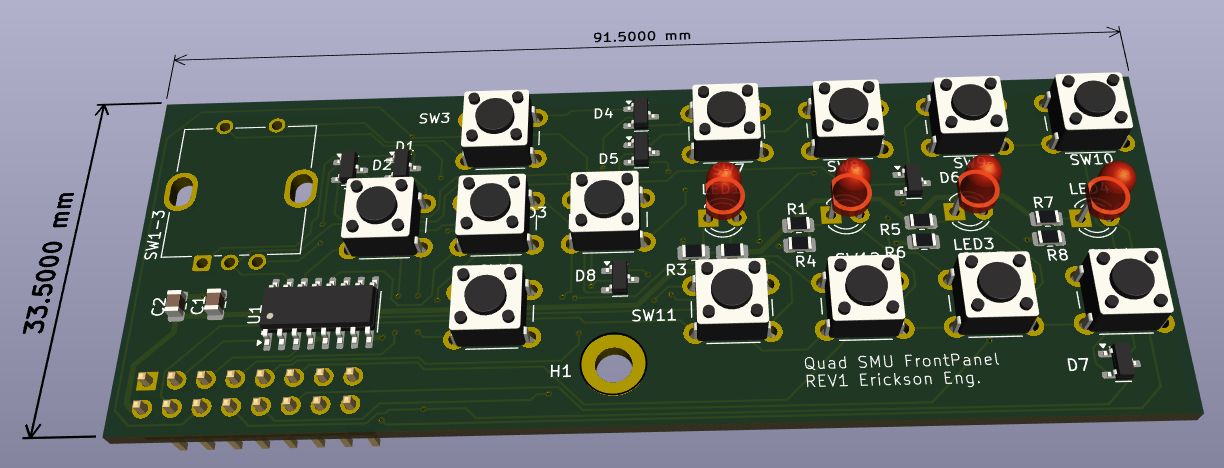
Here is the PCB so far.


Back to Dave's Home Page
This page was last updated 11/30/2024


