AC-DC and
DC-DC Common-Mode Noise Discussion
for DIY-SMU and other projects
DIY-SMU
project
The Problem: Common-mode noise
DC-DC converters are specified for output noise,
but almost never for common-mode noise. Common-mode noise
applies to all AC-DC converters and to all isolated DC-DC
converters. You can think of it as the
noise on the 'common' or output return. Or as noise that is
'common' to all outputs. Output noise is technically "normal-mode"
noise, the noise on an output with respect to the common. It does not apply to non-isolated DC-DC supplies such
as Boost, Buck, and Buck-boost. Also if an isolated supply is not
used in an isolated application (input and output grounded
together) then common-mode noise is much less of an issue.
A difficulty in specifying common-mode noise is that it cannot
just be measured directly as a voltage. The
noise contains frequencies as low as the AC line and up to many
harmonics of the switching frequency. Take any isolated AC-DC or
DC-DC switching power supply, and measure the output ground with a
10Meg 'scope probe whose ground is connected to the Chassis or
input Ground. You will observe significant junk. Pulses, noise,
ringing, and noise at the switching frequency, riding on
line-frequency noise. It tends to be
more of a current than a voltage. A
current measurement would be more accurate than a voltage, A sensitive, high-bandwidth current probe could
measure it, but I don't have one of these. So I use a simple
resistor to convert the current to a voltage. Common-mode noise may be best thought of as a
current, not a voltage. The load has a large effect on
the value.
All AC-DC power supplies use a capacitor from Input (chassis)
ground to the output common to reduce the high frequency noise.
Many DC-DC switchers also have capacitors from input to output
ground.
Here is a typical 3Watt DC-DC's common-mode noise, measured across
a 50 Ohm resistor. It is about 1 volt peak-to-peak. As a current
that would be I = V/R or 1V/50ohms, or 20mA p-p. Ideally the
current wold be in the uA range.
This
common-mode noise can show up as audible or ultrasonic noise
(higher frequency than audible) on audio or other critical
analog circuits. It can causes an unavoidable AC ground loop at
high frequencies. It can cause measurement errors in sensitive
electronics. This noise is one reason that the
highest-performance Audio and instrumentation often will not use
a switching power supply. Instead they often use line-frequency
transformers. In fact they often use single or multiple internal
shields between the primary and secondary windings.
It is very appealing to use these low cost AC-DC and DC-DC
switching supplies in many applications. Just be careful about
the common-mode noise, particularly if you need the switching
power supply output to float. If your system can be grounded
(non-isolated), grounded supplies generally reduce most of the
common-mode noise to acceptable levels.
Switching Power Supply
Common-mode Noise Issue
With any power supply,
either lab or otherwise, common-mode noise is an issue. When you
float a power supply, there is always some AC current flow from
the power supply ground to the chassis (AC) ground. With an AC
transformer based supply, this is usually a small amount of 60Hz
current due to the inter-winding capacitance between the primary
and secondary windings of the power transformer. With a linear
supply, the frequency (60Hz and some harmonics) and the
capacitance (20-200pF) and the 240VAC input causes about I = V /
Xc = 240/(1/2*pi*60Hz * 200pF) or tens of microamps. No big
problem, and the typical .01uF safety capacitor to ground shunts
out most of this current. In the case of a high-class power
supply or a precision instrument, the AC transformers are usually
double or even triple shielded with metal foil between the
windings. This shielding reduces the common-mode noise current
significantly.
However with a switcher and its high frequency transformer, the
frequency is not 60Hz, but the harmonics of the the fast rise-time
switching waveforms: rise times of 300V pulses can be about 100ns
causing pulses with harmonics of 10MHz or more. The transformer
windings are usually smaller, so the inter-winding capacitance is
a bit less. Just to meet radiated and conducted EMI, the
transformers are often shielded. You will sometimes see copper
foil on switching transformers.
Still, I see some pretty ugly looking common-mode switching noise
on many switchers. Manufacturers do not specify common-mode
noise, so how do you deal with it? How do you quantify it? Search for this problem on
line and you will find no specific data or techniques. In fact, to
meet EMI, Switchers are often tested with a short and heavy wire
from their DC common to the chassis ground. This effectively
shunts any common mode noise to ground. But if your application
requires a floating supply, you are on your own dealing with this
issue. Measuring the open-circuit voltage is interesting. You will
typically see a few volts of high frequency crud plus some AC. Why
not ~100V, since the switcher is switching hundreds of volts? The
answer is that AC-DC switchers do have a capacitor from AC to DC
ground, typically between .01 -.05uF. This is often a Y
safety-rated cap in case the ground of the system is accidentally
opened up.
Measuring Common-mode
Noise
To measure the
common-mode noise of a power supply, I use a simple current
measurement. A 10 or 50 ohm resistor has bandwidth out to the GHz
range. Wire a 10 or 50 ohm, 1/4W resistor between the chassis
ground pin and the DC common, usually V-. Measure the voltage
across this resistor with a 20MHz or 100MHz scope, and you have a
good indication of the high frequency common-mode currents flowing
through the supply. I did this on several switchers and as
expected, most had about 1V p-p of crud across 10 ohms or 100mA of
switching currents. But to my surprise, I found some
switchers are quiet, measuring less than 20mV across 10 ohms or
just 2mA! What do they know that the other guys don't?
To investigate this, I first measured the capacitance from GND to
V-. All supplies measured about .02uF, meaning that the
manufacturer typically uses a .022uf capacitor there. So I opened
up the bad and two good ones to see what the difference was. The
bad ones use a safety-rated, thru-hole, ceramic disc cap from V-
to GND. Seems reasonable. But the good ones use an array of 3x2
surface mount capacitors and much shorter and thicker PC
traces. And they mount the capacitors directly between the
V- and GND pins of the supply. This approach minimizes the circuit
inductance and therefore the high frequency noise. Nice.
Who is good and who is bad? All the CUI (V-Infinity) supplies I
measured (n=3) were bad. All of the TDK-Lambda supplies (n=2) were
good. I will be using TDK-Lambda switchers from now on when I am
concerned about noise.
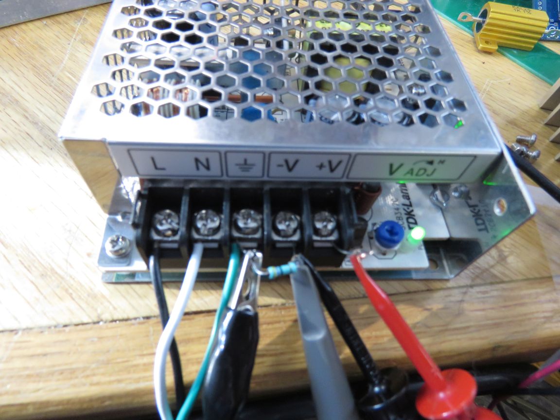
This is the TDK-Lambda LS50-24, showing the common-mode measuring
circuit. The red and black clip leads are for a 100 ohm (.24A)
load resistor. The resistor for measuring CM noise is 47 ohms.
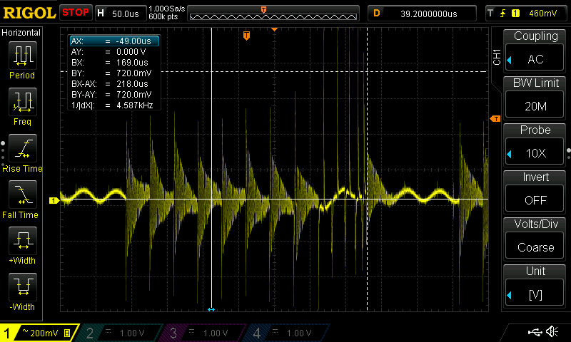
Here is the common mode noise waveform for the CUI VGS50-24 50W
AC-DC switcher. Lots of ringing (600mV p-p) and 1.5V spikes.
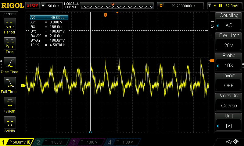
This is the same Common-mode noise measurment on the TDK LS50-24.
The voltage range is 4x lower, for 125mV p-p noise. Also no nasty
spikes.
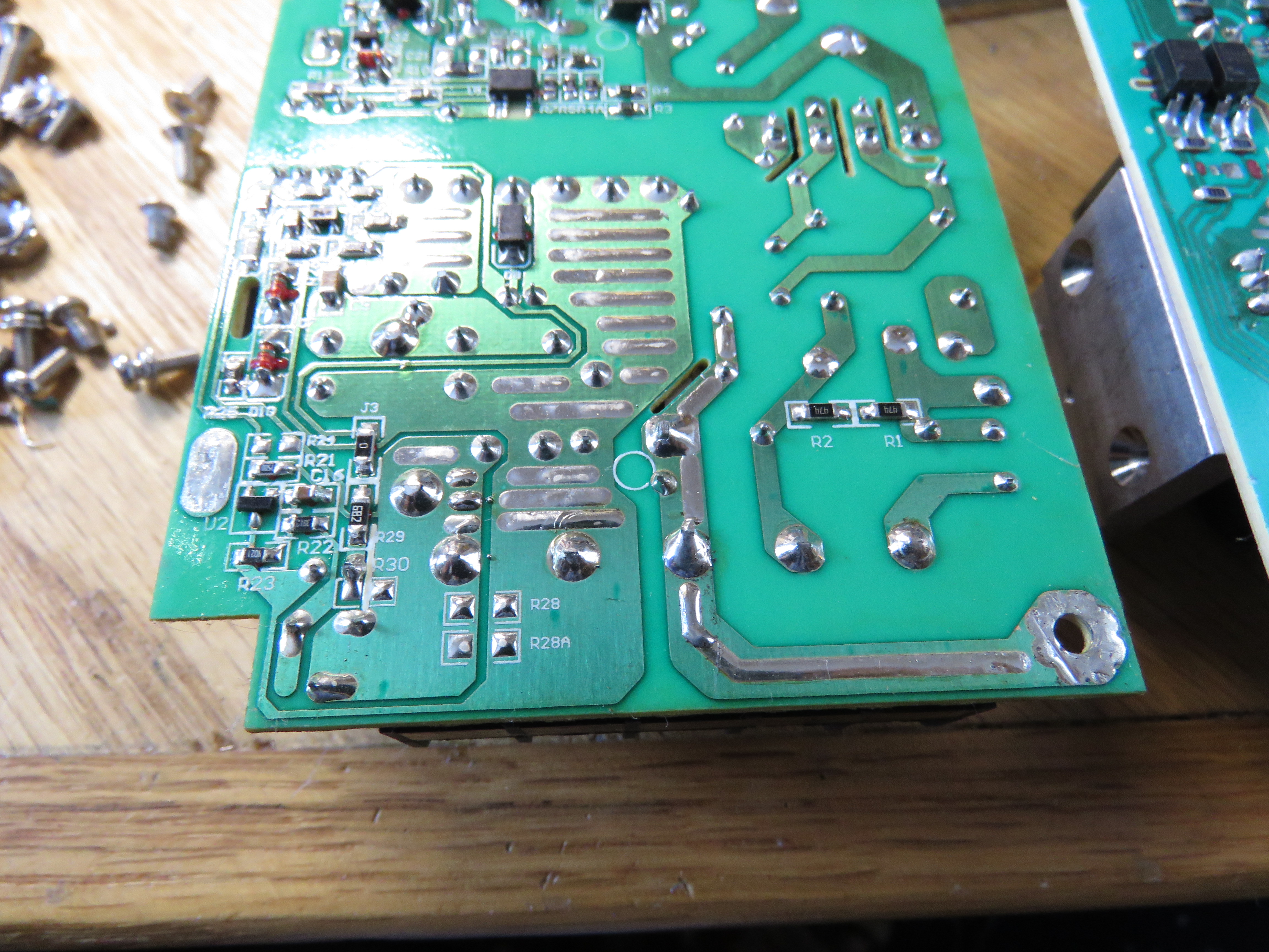
Here is the back side of
the CUI VGS50-24, showing the grounding layout. The small
white circle marks the location of a ceramic 10nF disc
capacitor between the heavy DC and AC ground traces.
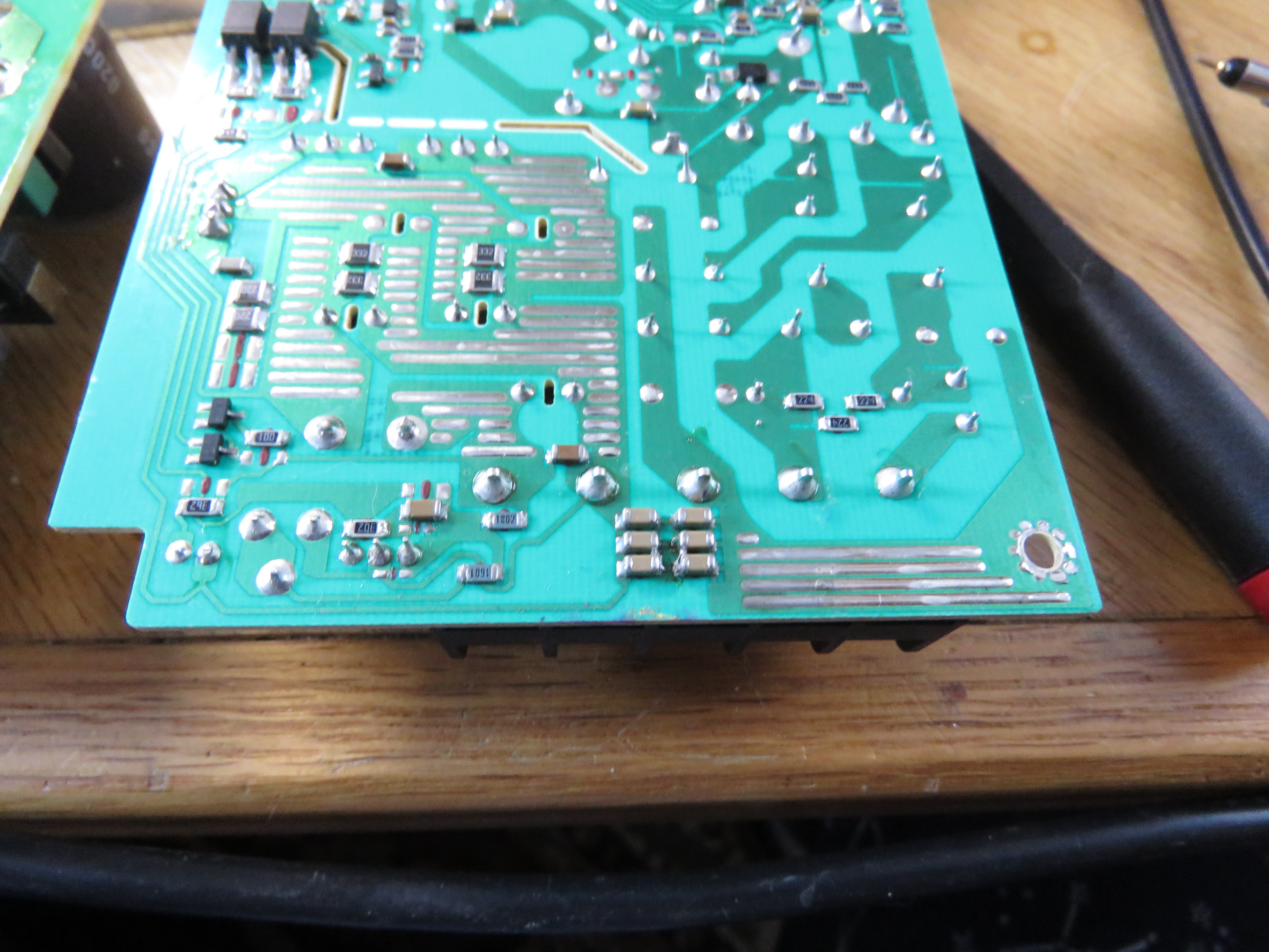
Here is the TDK grounding layout. Notice the 2x3 array of SMT
capacitors between the heavy DC and AC ground traces. The
capacitance measures 22nF, so the 6 caps are about 120nF each.
This provides very good filtering of high-frequency common-mode
noise.
DIY-SMU Rev2 Amp and Oscillation
When I built DIY-SMU, after fixing a few
instability (oscillation) issues, and one persistent noise. The
outputs were clean if they are allowed to float. But when I
grounded the -OUT, generally to the scope ground, the outputs
showed about 50mVp-p sine-ish
wave at 300-350KHz. I worked on
this on-and-off for weeks, but it remained. After eliminating all
the loop stability issues by removing or changing parts, it
remained. One problem is that the overall control loop is
complicated. It has a half-dozen opamps, plus the high voltage
amplifier. It has both voltage and current loops. I tried
improving my Spice simulation, but no instability. I built a
second unit with minimum circuitry: no ranges or modes, voltage
loop only. My debug approach was to reduce the circuit complexity
to the minimum that exhibits the problem. The stripped-down
version worked in FV mode, but the oscillation remained. After
much debugging, I noticed that the oscillation frequency
varies slightly with the +12V input voltage. This pointed to the
DC-DC power supply. I measured the inputs to the DC-DC and saw 3V
p-p of 300KHz! Finally the problem! Turns out the 3W Meanwell
DC-DC does not perform well with the common-mode (CM) choke. I
removed and bypassed the choke with a fixed ferrite bead, and the
output quieted considerably. Normally a common mode choke is a
good thing, reducing EMI on an output. However in an SMU like
this, that inductance plus the DC-DC capacitance is in the ground
return path. I decided the overall design was better off without
it. I replaced it with a 600ohm ferrite in the + input only, and a
short circuit in the ground. That's when I measured the
common-mode noise of several DC-DC converters.
DC-DC converter Common-mode noise
Measurements
After I found that the major output noise source
on the DIY-SMU project was caused by common-mode (CM) noise of the
DC-DC converter, I tested a handful of different manufacturer's
parts. No manufacturer specifies the common-mode noise of their
parts. CM only affects applications that require isolation. If
your application connects the output ground to the input common
(with a short wire), then this is less of an issue. And the value
of any 'Y Capacitor', a capacitor that connects the input to
output commons, also affects the noise. The effects of CM
noise depend on your system. It can cause measurement errors,
audible noise, radiated or conducted EMI, or other problems.
Here is a test summary spreadsheet, plus a few scope shots.
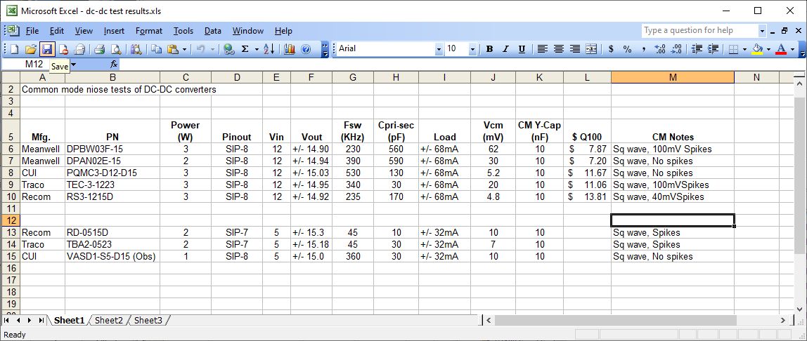
Meanwell DPBW03, the worst at 62mV
Meanwell DPAN02 comes in at 30mV
CUI PQMC3: Clean at
10mV p-p
And the cleanest, Recom RS3-1215D, with only 4.8mV
These were measured on a stripped-down DIY-SMU Main Board: only
the DC-DC and its associated input and output filter components,
plus resistor loads are installed on the test board:
DC-DCs: 12V to +/-15V
2W or 3W models
Original input filter Common-Mode choke
replaced with a 600 ohm 1210 size ferrite bead
Output loads are 220 ohm 1/2W resistors, +/-
68mA, 2.05W total
SIP 8 pin package
20 MHz scope bandwidth, ~20mV range, 10x probe
I also measured a handful of the smaller 1-2W 7 pin SIP devices.
These are 5V to +/-15V which I use on my 18b DAC project.
I use 2 different loads between the input and output common pins.
1) Relatively large 10nF Cap (Y-Cap) to filter
common-mode noise. This is what I intend to use in the product.
2) 50 ohm resistor load to observe the
high-frequency common-mode current waveform.
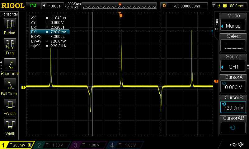
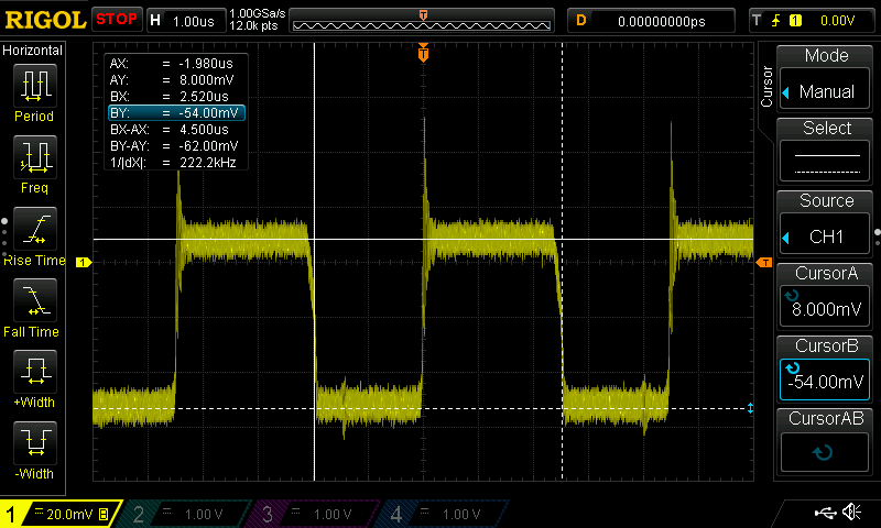
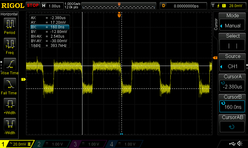
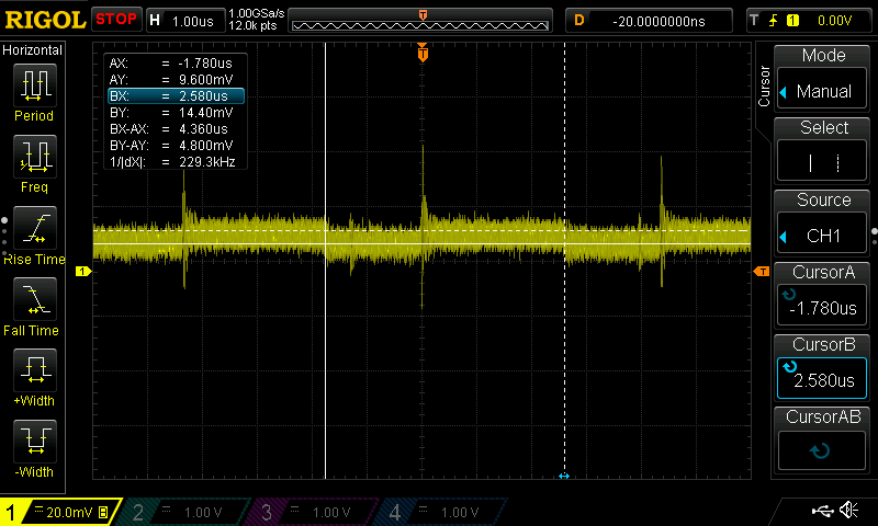
With the 50 ohm resistor, the waveform exhibits the common mode
current waveforms. These are narrow bipolar pulses ~100-500mV that
correspond to the switching transistor output transitions in the
DC-DC. With the 10nF cap, these fast bipolar pulses (impulses)
waveforms are integrated: V = 1/C * Int(I) which results in the
observed square waves. The amplitude of the square waves is the
integral of the pulse currents. It shows the energy (I * T) of the
pulses.
I only measured 2 devices for the 50 ohm test, the worst
(Meanwell), and the best (Recom). Waveforms are attached.
The Meanwell has a 590pF Y cap and exhibits a large area pulse.
Measurements are:
Input-to-output common capacitance, pin 1 to
pin 7, measured at 1KHz
Switching frequency
Common mode voltage and waveform, 20MHz BW
Output DC voltages
CM waveforms on some
Other stuff in the spreadsheet:
Qty 100 Price
Conclusions:
Noise seems to be a function of price. High cost ~= low noise and
vice-versa. Since I originally picked the lowest cost device, I
got the one with the highest noise (Duh!). I plan to change from
the MeanWell to the Recom part.
The combination of the Meanwell DC-DC and a common-mode choke is a
bad choice. The MeanWell without the choke is an improvement. The
Recom with the choke is even better. Next I will try the Recom
without the choke.
The Cpri-sec capacitance indicates the value of the built-in
Y-caps. Units with higher value caps tend to have lower high
frequency spike noise. Spike noise can be harder to filter out
with an external Y-Cap.
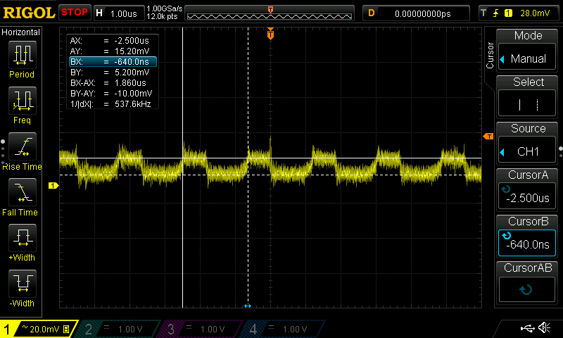
TDK-Lambda CC6-1212SF

I tested a TDK-Lambda CC6-1212SF dc-dc module. It is a 6W, 12V to
12V, single output supply. The CC1 through CC10 products feature a
wide 2:1 input range, and adjustable and regulated output. They are
flyback types with a switching frequency of 640KHz. The common mode
noise is pretty high. I measured 200mV p-p of spikey common mode
noise across a 50 ohm resistor. The capacitance of the input to
output is about 100pF, probably from transformer inter-winding
capacitance. With a 10nF Y capacitor, the CM noise is a smoother but
still large 100mV. Even with a 50 ohm resistor.
Building a quiet switcher
There are several common approaches to making
switchers quieter.
- Reducing switcher rise and fall times
- Using a resonant supply to reduce the rise
and fall times
- Transformer inter-winding shields
- Adding input and output normal-mode filters
- Adding Common-mode chokes to input and/or
outputs
At Analogic, I worked on very precision 20 bit
2MHz digitizer and waveform generator instruments for a big ATE
company. It required multiple supply voltages, all at very low
noise. It provided +/- 17V, and every critical amplifier had its
own +/- 15V power supply regulators and filtering, built with
dozens of tiny 78L15 and 79L15 regulators. This is the only time I
have seen this approach used. Anyway, the power-supply consisted
of an off-board box that provided a clean, isolated 100HKz
sine-wave AC via a single 3-wire shielded-twisted cable. If I
remember correctly, it was center-tapped. On the instrument was a
small, shielded module that provided transformers, rectification
and filtering using many, large ceramic capacitors. This approach
worked well, but if you looked real close, there was always a tiny
100KHz noise spur on the instrument outputs or ADC input caused by
the power supply.
I think that in addition to lower common-mode noise, a resonant
switcher also tend to have lower diode switching noise, since the
output side rectifier diodes are not being asked to turn on with
nice slow sine-waves instead of 10-100nS rise-time input
waveforms.
The Keithley 236 SMU uses an AC transformer to provide its +/-
120V supplies as well as other internal supplies. I think the main
AC transformer is triple-shielded to allow this instrument to
measure and source currents down to the 1 pA levels. The 237
High-voltage version adds a +/- 1200V power supply. It uses a
Resonant design which drives the primary with diode rectifiers and
heavy L-C filters. Resonant converters apply a
high-frequency sine wave to the transformer, not the usual square
wave. The 237 supply starts with a PWM full bridge, then filters
it with and L-C filter to convert to a sine wave. For a great
discussion of this power supply check out Marco Reps.
He built his own 237 power supply board in order to upgrade
his 236 to a high-voltage 237. Marco is my hero.
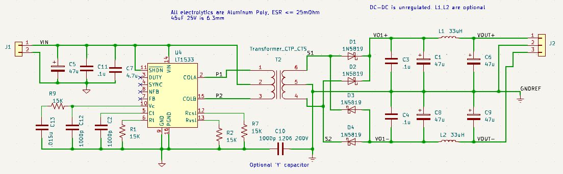
LT1533 Low Noise DC-DC
Jim WIlliams at Linear Tech (R.I.P.) recognized
the problem of isolated switching supply noise. In his excellent:
Application Note 70, "A
monolithic switching regulator with 100μV output noise:
Silence is the perfectest herald of joy..." He uses a LT1533 switching regulator which
offers reduced rise and fall times. This is a decent approach, and
can be built with an off-the-shelf transformer. This IC requires
feedback to operate though, and most of the app-note circuits do
not have isolated feedback.This excellent treatise shows some old
tektronix techniques to reduce power supply noise. It doesn't
really address the common mode issue, but his techniques to make
low noise supplies also will help reduce common mode currents.
The lT1533 IC uses a push-pull transformer. Unlike flyback and
h-bridge types, push-pull transformers tend to reduce common mode
noise simply by having the two halfs of the primary out-of phase.
One side's common mode noise cancels out the other side....
Push pull converters can be open-loop (unregulated) or
closed loop (regulated). For closed loop design, a ''forward
converter" design is used. The transformer drives a D-L-C filter
where the L-C filter converts the PWM duty-cycle to an output
voltage, similar to a Buck converter.
For push-pull open-loop (unregulated) design, the transformer is
driven with a 50% duty cycle and the output filter is D-C with
optional D-D-L-C.
Art of Electronics: The X-Chapters
Another excellent source for
info on low noise power supplies is Art of Electronics: The X
chapters, 9x.14 discuss common-mode noise, one of
the few places where this subject is discussed. They dove
into the problem big-time, using:
- Push-Pull design
- Sine wave drive
- Transformer shielding
- Common Mode choke
Maybe I have
to build the AoE X-files solution. To get minimum CM
noise, they applied all of these techniques. They got the common
mode noise down to 1mV p-p across 50 ohms. 20uA is quite good for high frequency common mode
current.
They address it using a differential sine-wave
driving two Class-B amplifiers. Pretty brute-force and high
component cost IMHO. And inefficient due to the linear
amplifiers. A more efficient way to get a sine wave is to
use a resonant driver.... How about a class D audio
amplifier? These are pretty cheap and efficient.Getting
clean-ish sine waves at 100KHz or so, not so good.
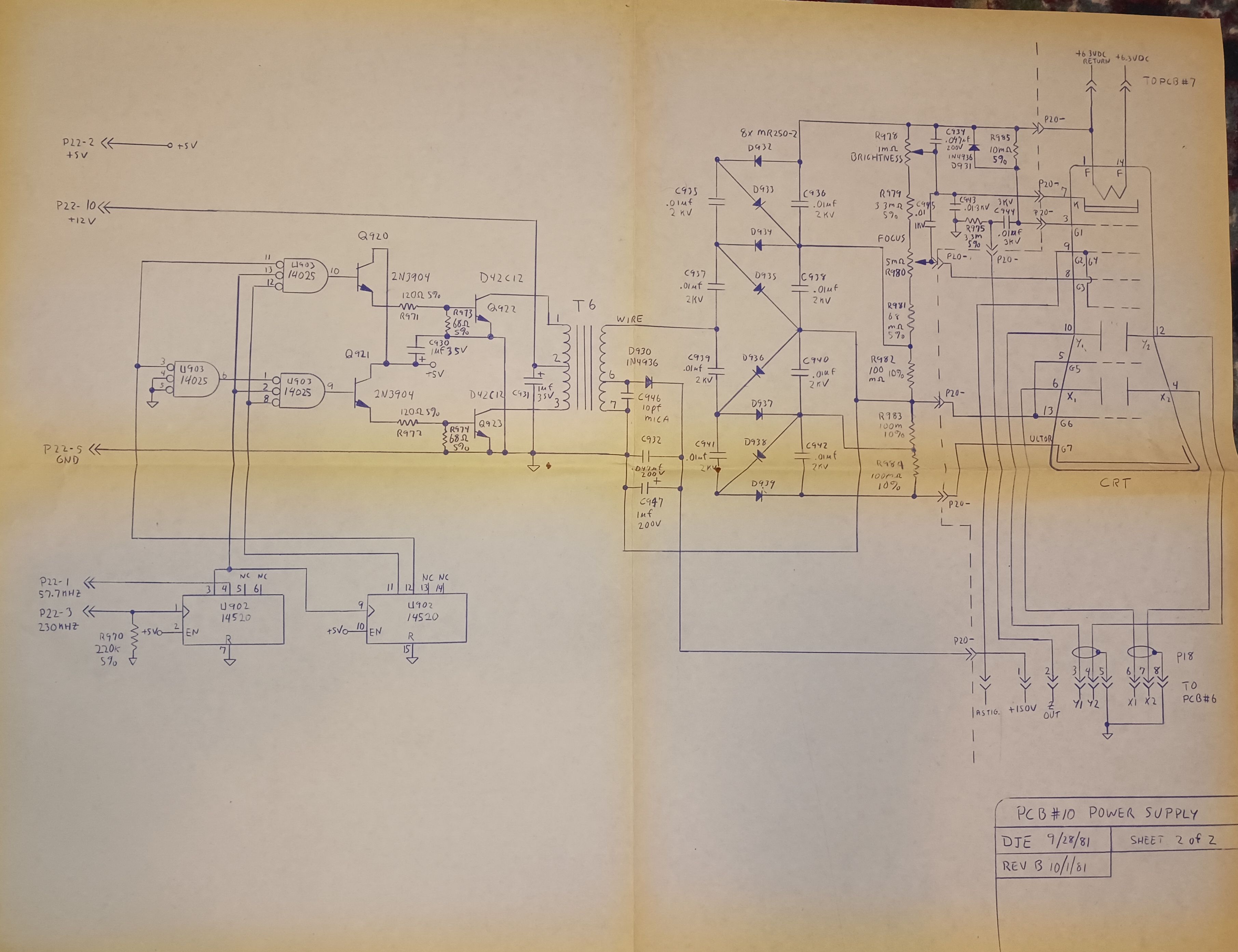
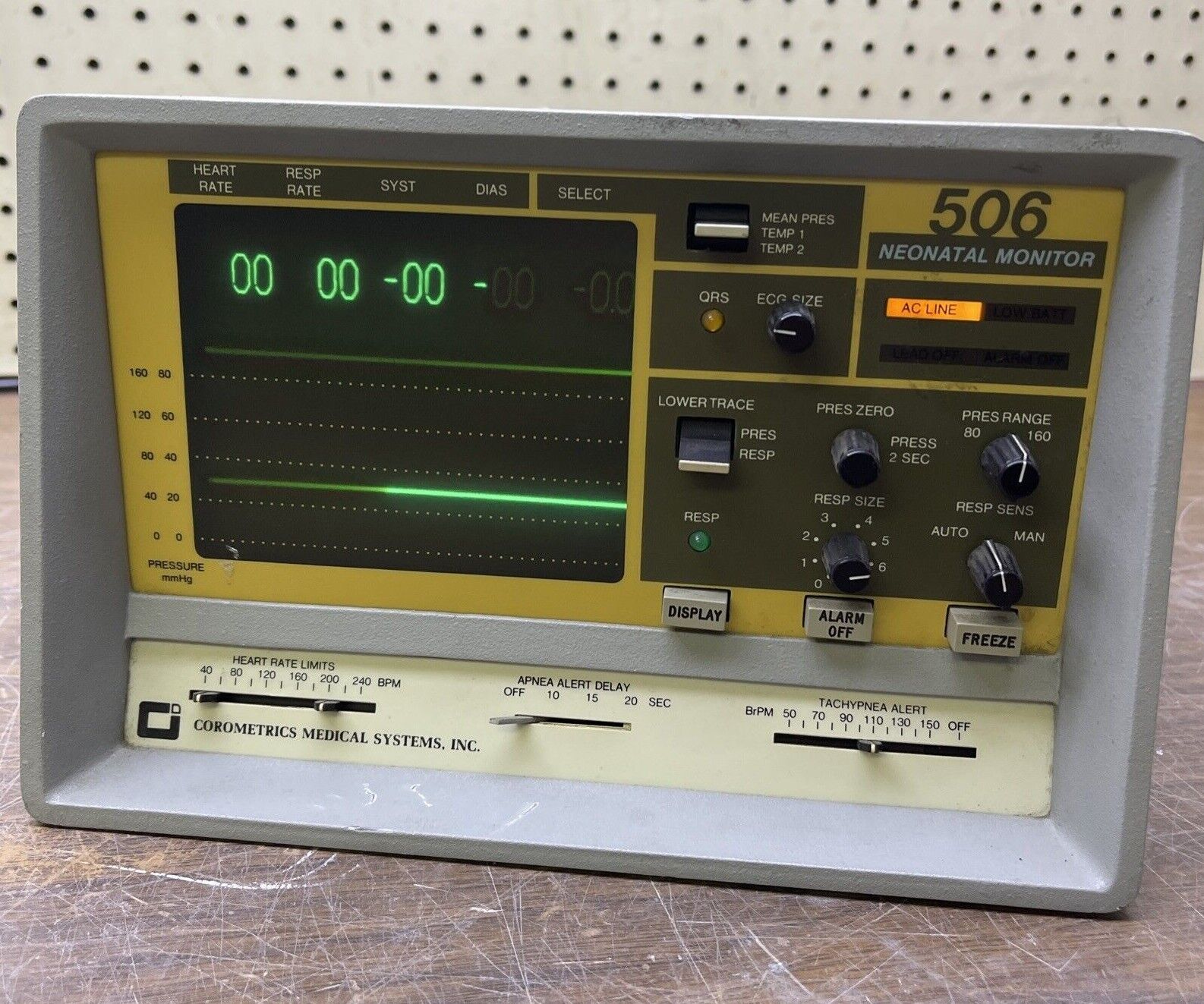
Ancient semi-resonant HiV power supply design
Here is an ancient Circa 1981 high voltage power
supply I designed in my youth for a medical monitor, the
Corometrics 505/506. It provided high voltages +/- 2KV (I think)
for a 5" CRT, and +150V for the
deflection amplifiers. What is cool
about it? The entire medical monitor drew ~6W including several
isolated medical front-ends and this CRT. It was portable and
battery powered from a 12V gel-cell. This
DC-DC ran open loop, constant frequency, constant +12V in. The
transformer was a big 3019 potcore. See the schematic below in its
yellowed blue-line and hand-drawn glory. The tricks were:
- Use narrow PW drives, class C, push-pull. It only drove the
transformer during the peaks of the 29KHz sine wave. Drive was
12.5% (1/8) duty cycle.
- Use a fixed 10pF tuning capacitor (C932) to resonate the
inductance of the 150V secondary
- Clean sine wave drive with flat-top and flat bottom
- Voltage multipliers for the +/- 1200V
- No unnecessary harmonics, no fast diode
tun-on, so low noise.
This worked because of the
relatively high inductance of the +150V secondary winding. The
10pF capacitor was selected to make the switching waveform
ideal. Resonance was about 25% faster than 29.7MHz or about
36MHz. Don't laugh at my 4000-series logic. Two cascaded
counters were used to make sure the Q0 (U902-13) output that
sets the pulse width was a few nS early, to avoid decoding
glitches. Transformer T6 is a 3019 potcore, carefully wound to
handle the high voltage. All the logic and power supplies in the
system were derived from a single clock crystal to eliminate any
random frequency beating effects. Had some pretty sensitive
analog circuitry.
Not a bad design for a kid 5
years out of WPI. I did have a predecessor's design as a
starting point, which is always a good idea. I'm not sure if
such an approach has any practical use on modern low or
mid-power DC-DC converters.
As project lead on this design in 1981, I'm still pretty proud of
what we built back then. Here is our Corometrics 506 Neonatal
Monitor. Couldn't have done it without a great team: Jeff S, Dave
L and Wayne C.
Building a low noise AC-DC power supply
I recently (2022) built a music server using a
Raspberry Pi and Volumio Software. I wanted a quieter power supply
than the usual Raspberrry Pi switching wall-wart. After watching Marco
Reps excellent video on the subject of common mode currents
in isolated supplies, I realized that there is a trick that can
reduce AC transformer common mode current considerably. Here in
the US, line voltage is 120VAC. Since many AC transformers have
dual primaries, one of the 120VAC primary windings can used for
power, and the other winding is wired out-of-phase to the other.
The second primary's voltage cancels out the main primary from a
capacitive coupling point of view. Split-core transformers (with primaries isolated from
secondaries) already have pretty
low common mode currents, and this trick reduces the current by
another 10x. It's a bit of a hack because it only works on
100-120V AC systems. To worh at 240VAC, it would be necessary to
have two 240V windings on a transformer. It could be done, but I
know of no off-the-shelf transformers like that. Check it out on
my Raspberry Pi
Power page.
This trick demonstrates that
push-pull power supplies have lower common mode currents than
unbalances types.
Further work to do
I would like to experiment with the LT1533 and
some off-the-shelf and custom transformers. Unfortunately this
part is 12V maximum supply (limited by switch output voltage) and
is $15 at Digikey.
I would like to continue investigating simple and low power
resonant power supplies to make sine-wave drive. Or even
higher power supplies.
I would like to investigate DIY electrostatic shields on custom
dc-dc transformers.
I would like to build a quiet, higher power, push-pull driver.
Preferably that is less dependent on a specific IC. Maybe:
- UC3825 or similar low cost FET Push-pull controller, +12V.
- 100KHz to reduce FET switching losses since FET drive will be
slowed
- Add RC filter ~200nS Tc to slow FET Tr and Tf
- Then add emitter followers (complimentary NPN/PNP) to improve
FET drive and reduce FET Miller capacitance.
- Could be regulated (LC output, optical feedback) or
unregulated (49% duty cycle, no L)
- High power:
- Input +24V 5A (100W) or +48V and 5A (200W)
- LT1683 low noise push pull does al this and with tight control
over current and voltage slew rates. It looks good for
higher Vin / higher power DC-DCs
- External FETs
- $12
- Uses small capacitor networks to control slew rate
- Eval Board DC477 is 48V to 5V 2A
- Could modify to use other transformers, but need output
circuit....
For a low power quiet DC-DC:
- Low power, quiet: 3-5W
- +5V or +12V in
- Small custom potcore transformer with +/- 17-18V outputs to
allow linear regulators down to +/- 15V
- There are few or no +/- 17V DC-DC's
- Flexible transformer mounting to allow custom and
off-the-shelf transformers
- LT3999 driver? No slew rate control, Unregulated only.
- LT3439 Slew rate limited, 1A, $8. Unregulated
- LT1533 $15, Slew rate lim. Can be regulated or unreg.
- TI
- Definite LC output filter
Since layout is critical, maybe design / build a few custom
boards that can be used as modules
- Low power 3W, 5 and 12V to +/-12 or +/-15V
- Single chip, small potcore, filters, optional LDOs
- Optional open or closed-loop
- Higher power 12V, 24V and 48V to whatever
- Transformer windings and output parts determine output
voltages
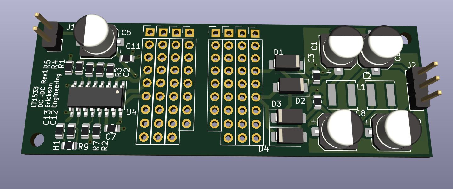
Here is a first pass low noise DC_DC LT1533 board. The proto area is
an attempt to accommodate different transformer footprints. RM cores
will fit since their pins are on a 0.1" grid. Same with many Wurth
transformers. Others will need some hand wiring. This project is
mostly an exercise in transformer experimentation. I left out
optical feedback (closed-loop) and LDO regulators, too many choices,
and some won't need them. You probably want the LDOs on your
application board. It's a starting point... Time to order
boards and parts.
The BOM cost including a $3 PCB is about $33. Assumes $10 for a
transformer. Wurth ones are cheaper.
Transformers
I've been looking at various off-the-shelf
transformers for low power DC-DCs. MIdcom/Wurth, and Eaton look
promising. These are specified in various TI and Linear App notes
to be used. Many of these transformers are designed for Gate-drive
applications or communications. So the turns ratios are generally
pretty limited. Many are not push-pull on both sides. Also these
are not shielded, and most use E cores or toroids. I rarely find
one that meets my needs. If you want something done right, do it
yourself. I'm an old potcore guy. potcores are great, easy to wind
and assemble, contain the B-field well, and are pretty
flexible. I have a 40 year old assortment of them, old 3B7 and 3B9
ferrites. RM cores are kind-of the modern upgrade to potcores.
Similar to potcores, they offer more flexible bobbins, simple
clips for assembly, lower cost and more efficient board space. In
AN70,
Jim Williams does a nice comparison of core types.
However... here is the Wurth
Push-Pull transformer listing, pretty comprehensive. Some
decent and interesting turns ratios here. 5V input to +/- 5, 12,
15 and 17V are interesting. Some are E-cores, some are
toroids. Digikey stocks about half of them, prices are pretty low.
However I found a fundamental problem. The LT1533 that I am using
operate up to 250Khz clock rate. But the Wurth transformers, with
their tiny toroid cores and low inductance, need 200Khz minimum.
But, but, it's a trap! The transformer specifies the voltage drive
frequency, and the LT specifies the clock frequency. The voltage
output of the LT1533 is 1/2 of it's clock. So it can only go down
to 250KHz / 2 = 125Khz. Darn. I tried overclocking the LT1533 to
300KHz, a compromise frequency for both it and the transformer,
and got OK results. Looking at LT3999 and
In searching for ways to reduce transformer leakage inductance, I
came across this excellent book on transformer design: Transformer
and Inductor Design Handbook (Electrical and Computer
Engineering) 4th Edition by Colonel Wm. T. McLyman, The
author was a transformer guru at JPL and many big space programs.
There is a section on low noise switchers, using a semi-resonant
design used in various JPL programs including Hubbell telescope
and Mars rovers. I'm working on a rotary transformer project, and
sure enough, there is a chapter on rotary transformers! Great
resource. The paper version is expensive, the Kindle version is
reasonable. With some rooting around on-line and signing up for
some spam, I found a free PDF. I read all 700 pages and it
is very good. Technical, but it steps you through the math. Lots
of fairly simple math for any transformer design.
LT1533: No 12V operation
I received the LT1533 boards, built them up, and
found a few small design errors. Mostly missing grounds which were
fixed with rework wires. I forgot to add the 25nH inductance
(wire) on pin 16. To get 50% fixed duty-cycle, ground the DUTY
pin, and the FB pin must be below 1.2V, about 1.0V. But if FB is
below 0.4V, the clock oscillator slows down. This is a slow-start
feature that runs it at lower power until the part is fully
powered up. It operates with a lovely and clean trapezoid
waveform. Input and output currents are clean. The rise time
of the voltage and current are controlled by resistors.
The part works with 5V in, and up to about 7-8V. But I couldn't
get it to work reliably at 12V in. The part is rated at 12V in,
and the switches at 30V. Some of my applications need 12V. At 10
or more volts, it was going into thermal overload. If you look
closely at the LT1533 data sheet and at AN70, all the application
circuits are 5V input. At 12V, even with a high inductance
transformer, it goes into current limit. With a beefy, high
inductance (540uH per side transformer, the SOIC-16 package
overheats in a few seconds. With even higher 1.2mH per side, it
runs for about about a minute at +12V before overheating. This is
with or without the output winding connected and loaded.
Using a 1 ohm resistor in series with V+ to the transformer center
tap, I was able to measure the primary current, and found the
problem. The current pulses high during the switching transitions,
which were about 15% of the clock period. This was too long for
12V operation. Rvsl
(voltage slew rate, pin 13) controls the output slew
rate. At 12V, the transition time is 2.4x more than at
5V. Reducing the Rvsl resistor
from 15K to 6.8K made a big difference. Still I'm surprised
at the high current draw during the transitions. But it now works
at 12V! It still gets hot, over 70C with no load. But it can put
out as 5W or so without overheating or current limiting.
In troubleshooting the problem, I got the LtSpice LT1533
simulation fixture working. Of course it doesn't go into thermal
shutdown like the real circuit does. I modeled the output
transistor power (Vcola *Icola) and it seems fine with a 1.2mH
transformer. No explanation yet why it gets so hot in the real
world. Apparently the Spice model
doesn't model the transistor slew current very well.
I am thinking of a big power supply / transformer test board,
following in the footsteps of the AofE X-Chapters work.
- High power LT1683 low noise
switcher with FETs for
- 12V, 24V or 48V input
- Various outputs up to 5A
- Mid power analog Sine and
trapezoid waveform generators
- Single-ended or
differential
- Variable frequency
- Variable amplitude
- Sine wave
- Trapezoid with variable
slew rate edges
- Single-ended or
differential analog driver
- Sine wave up to ~30V p-p
per side, 55V diff.
- A few amps
- Accepts varying power
supply voltages
- Class B high-speed
buffers
I'll use my SG3525 proto board for now, and plan
to build up a LT1683 board for the
higher power applications. It should do voltages up to 24 and 48V
and at much higher power.
Dave's Home Page
Last Updated:
10/2/2023