LeoLed: 
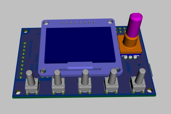
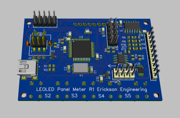
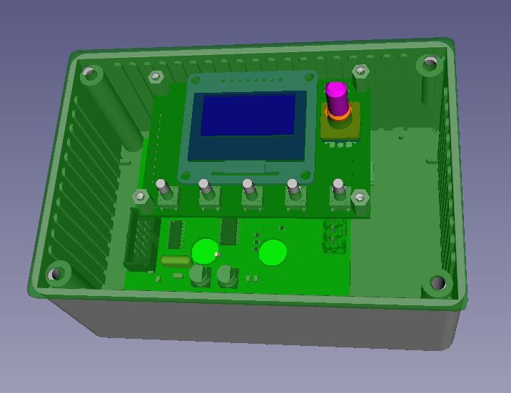
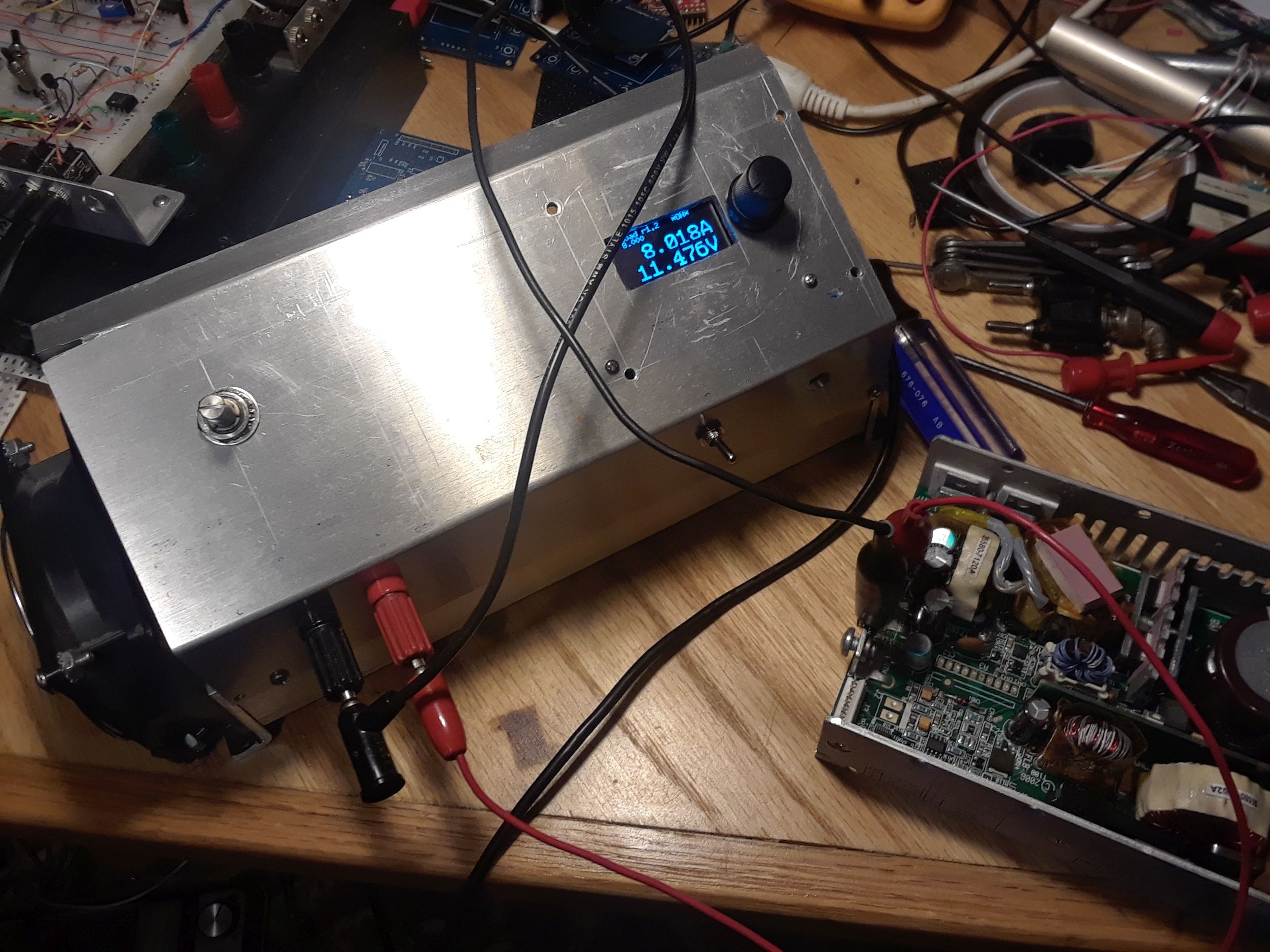
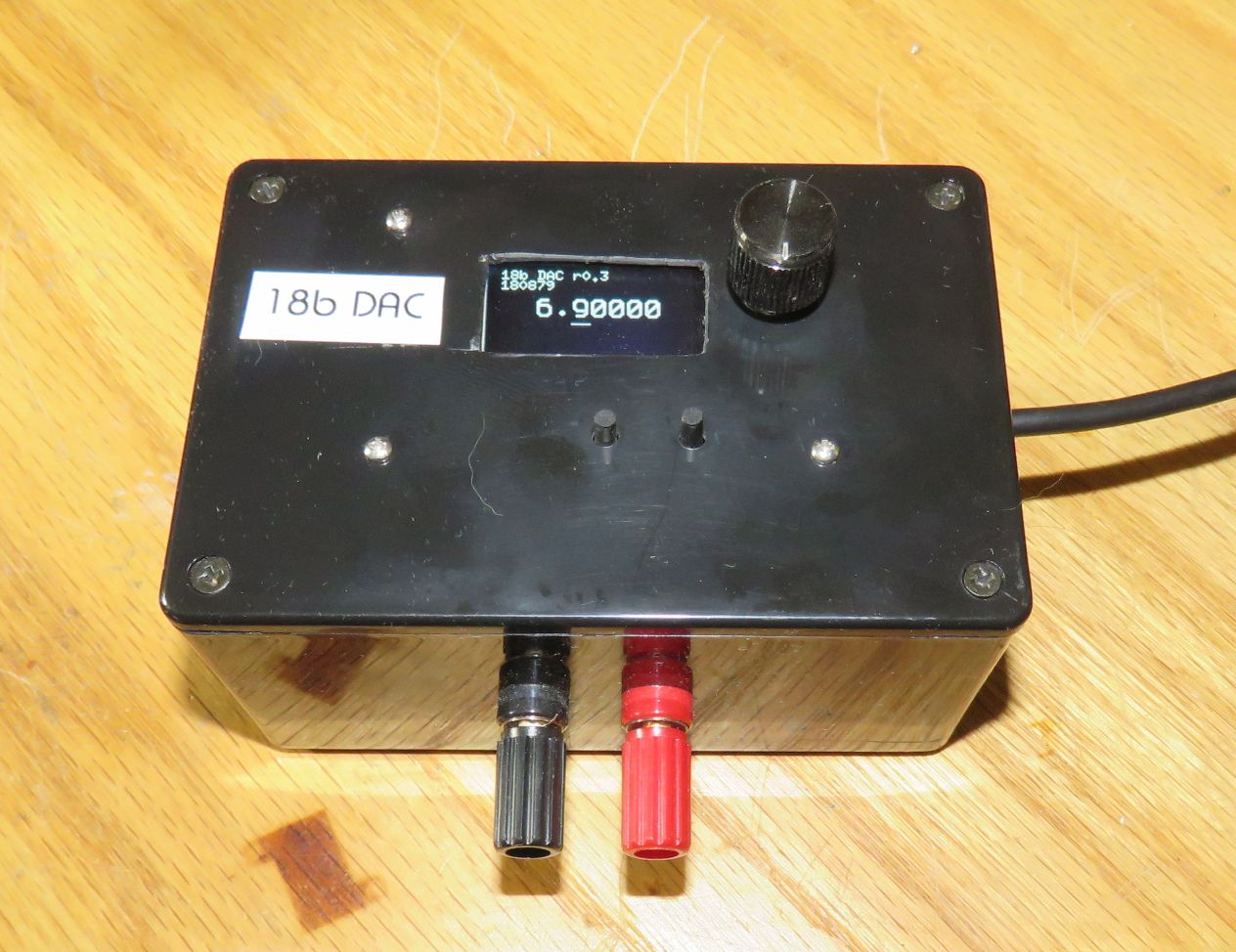
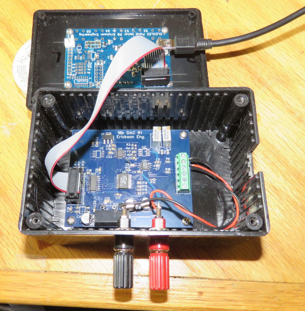
Arduino panel meter and front panel
The Blog for this project (not yet!)

The 
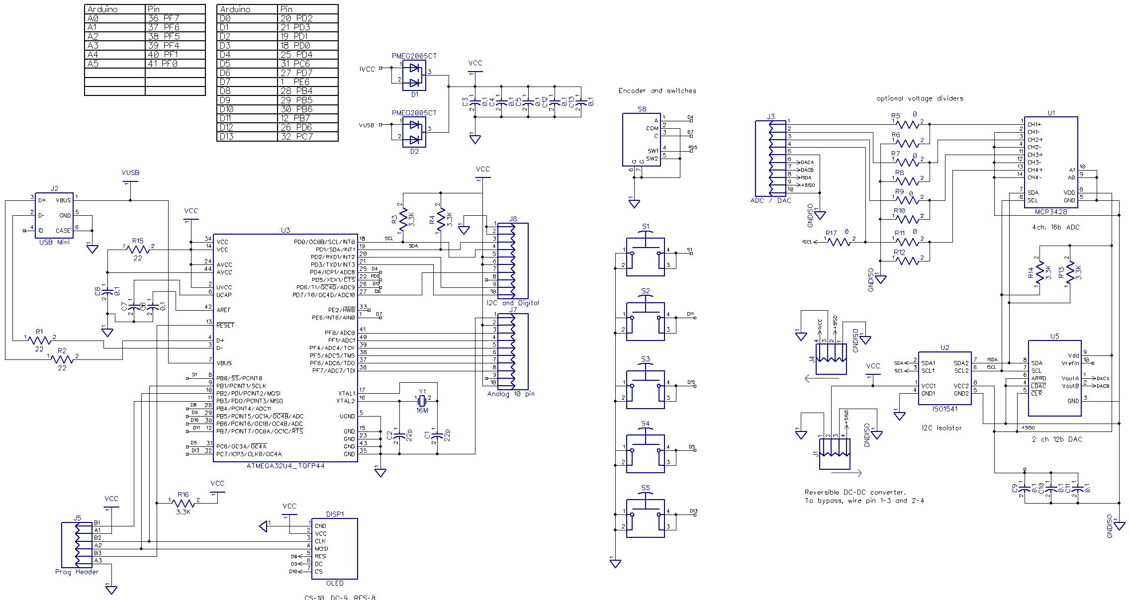
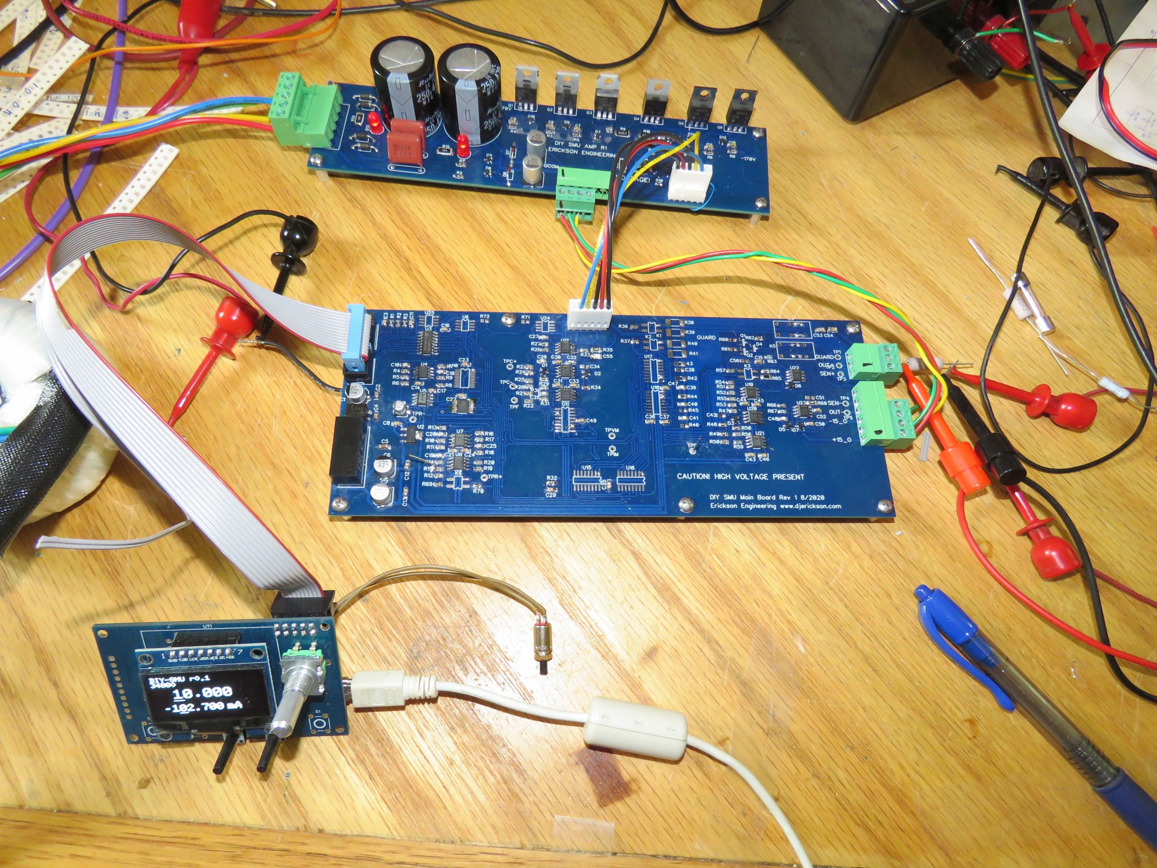
Schematics, PCB files are here

leoled

Introduction

Panel meters are super useful. They can be used for voltage and current measurements and many other analog parameters. They are cheap and perform well. But off-the-shelf meters are pretty limited. Your display format is generally limited to 3.5 or 4.5 digits. Maybe you can move the decimal point. Some display 2 parameter. My old projects used LCD or LED panel meters. I have even designed one or two into commercial instruments. But the minute you want something special or different, sorry.  With the advent of Arduino, small OLED displays and low cost ADCs, and isolators the need for a flexible and open panel meter seems obvious.

Then when you implement a graphics display and a few controls, this can also be used as a user interface for various projects such as power supplies, power monitors, e-loads. USB control over your projects comes nearly for free.  I am a bit surprised that there are no other products that do this. So I designed LeoLed, my panel meter and front panel. Currently I use it for a few projects:
When I conceived of this thing, I thought it should have the following capabilities:

Design

Previously I built a panel meter with a small 8x2 character LCD. It worked, but was very limited. The LED backlight made it tall, and the 8x2 character display was very limited. 16x2 displays would have made it too large. OLEDs allowed flexible, low cost and bright displays. No backlight, low profile, small size and low cost.

Here is LeoLed design schematic. On the left is the processor, USB, programming and OLED connectors. J8 is the I2C and digital expansion connector. J9 is the analog expansion. I use J9 it for SPI expansion and use bit-bang code to control my 18b DAC and DIY-SMU projects. 

The middle is the encoder with switch, and the 5 push-buttons. These use built-in pull-up resistors on the processor.

On the  right is the 5V power isolation DC-DC, and the I2C isolation U2. Note that the 5V power DC-DC is reversible: power can either come from J3 (isolated) or non-isolated from USB, or from an external +5V connector on any of J7, J8 or J5. The DC-DC can be bypassed to save $6 if isolation is not needed. 

U1 is a 4 channel, 16 bit Delta-Sigma ADC from Microchip, MCP3426. Easy to use and low cost.  U5 is a dual 12 bit DAC. The resistors between J3 and U1 are optional voltage dividers. For bipolar voltages, plan to use the low voltage +/- .256V range. With this range the ADC input can be as much as -.3V below ground, allowing accurate bipolar measurements. the 16 bits are bipolar, so it's really 15 bits plus sign. If you need more bits, the Microchip 18b part MCP3424 can be substituted. I haven't done this.
 

sch


Here are 3D models of the board, and in the 18b DAC enclosure. Board 3D models are from DipTrace. Box 3D model is from FreeCad.
.
3dtop

3dbot

3dbox

This is a LeoLed controlling my E-load project. Before LeoLed, I used a 10-turn pot to set the current and an external DMM to read the current. And another DMM to read the voltage. This is so much better. It uses the 16b ADC to read current and voltage, the DAC sets the current.

psload with leoled

Here is a LeoLed controlling my 18b DAC, precision voltage source. Works swell. The top board is the back of LeoLed, the Arduino Leonardo with OLED display and controls. The bottom is the 18b DAC board.
18b dac
18b dac guts


And here is a LeoLed controlling my DIY-SMU project.

diy-smu


The Blog for this project
  Dave's Home Page

Last Updated: 9/17/2020