LM399
Reference: Precision 10V voltage source.
The
Schematics, PCB files, and BOM are here
Introduction
The LM399 voltage reference is used for many
precision instruments like multimeters up to 6.5 digits. These are
simple to use thermally regulated voltage references that can
provide better than 1ppm/C stability. The problem with these is
that they use a 7.1V buried zener diode with an accuracy of about
+/3%, not precise by any means. But they are very stable. The
challenge is how to build a precision voltage reference from these
parts.
For the ultimate stability, 7 or more digit instruments use the
LTZ1000 reference. This part is more complex and more expensive.
The issues with the LM399:
Inconvenient voltage 7.1V. 10.000V or
5.000V would be more useful.
Poor accuracy +/- 3%
To generate 10V from 7.1V requires an amplifier
with a gain of 10.0 / 7.1 or a gain of 1.408. For this, two
precision resistors with a ratio of 1:0.408 or 2.45:1 are needed
plus a precision, low-drift opamp. But that isn't enough. The
ratio needs to be both adjustable and stable. These are
conflicting requirements. Also the ratio of these resistors is
more important than the absolute values. And temperature drift
causes changes to this ratio. This is a fundamental problem
affecting precision circuitry. The fix is to not use individual
resistors but to use a resistor network with both resistors on the
same substrate. By building them on a common substrate, the
advantages are that the two resistors:
Are built with the same formulation of
materials
Are built at the same time
Share the same temperature rise
Have similar tempcos, so the ratio tempco
is lower than the individual resistors.
Precision resistors are usually 5 to 20 ppm/C.
The best resistors, Metal Film types, are 2ppm. But when built as
a network, the ratio match can be as low as 1/10 or less, so 1 to
2 ppm or better. Resistor networks have critical specs
called ratio match and ratio tempco. Because the two (or more)
resistors are built on a common substrate and a generally much
better than the tempos of individual resistors.
The problem is that precision networks are often custom designed
and have high cost and long lead times.
The next problem is how to correct the 3% error. Variable
resistors (trimpots) are notoriously not stable for tempco or
for mechanical stability.
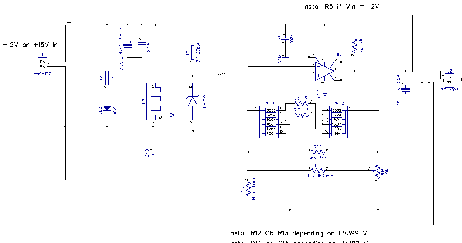
Design
The answer to these design problems is to use
three resistor networks in parallel:
A precision, matched network with 2.44:1
ratio and very low ratio tempco (<= 2ppm/C)
Additional 25ppm precision fixed resistors
to pull the output voltage closer to 10.00V: Hard trim
A trimpot to pull in the last error to
0.
Maxim makes off-the-shelf resistor networks in
an SO23 package with various common ratios and 2-1ppm ratio match.
Many of these are common integer ratios, but one model is 8.571K / 21.43K which is 2.500 : 1.00. This is close
to the desired 2.44:1
The additional fixed resistors are selected as a function of the
LM399 actual voltage. This technique, also known as a 'hard trim',
uses a spreadsheet to determine the trim resistor to use for a
given LM399 voltage. One resistor provides a correction of
about +/- 3%. By using a commonly available 0.1% 25ppm resistor
here, these contribute only a few percent of the total ratio. Lets
say it adds 2% of the ratio. That means that its tempco of 25ppm
is multiplied by about 2% or about 0.5 ppm/C. These are crude
calculations.
Then the last maybe .1% of the ratio can be corrected with a
trimpot plus a fixed 25ppm high-value resistor.
If you are building only a few of these, you would measure your
LM399's voltages, determine which resistors you need with a
spreadsheet, and order them. If you are building lots (10's or
100's) of these, you would order a range of resistor values,
and have them on hand.
Why does this work? It works because the main resistor network
contributes most of the precision ratio and therefore most of the
tempco ratio error,
the 'hard trim' provides a few percent LM399 accuracy correction
and therefore only a few percent of the tempco error. Finally, the
trimpot provides about 0.1% of the trim and therefore only .1% of
the tempco.
Trimpots tempcos are generally specified as a change in resistance
vs temperature. Makes sense since they are variable resistors. 20
turn cermet and wire-wound trimpots are generally 100ppm/C. However if a trimpot is wired as a voltage
divider, it is similar to a matched resistor set, and its
resistance change is not so important. What is important is its
ratio change (tempco), which should be better than the resistance
tempco.
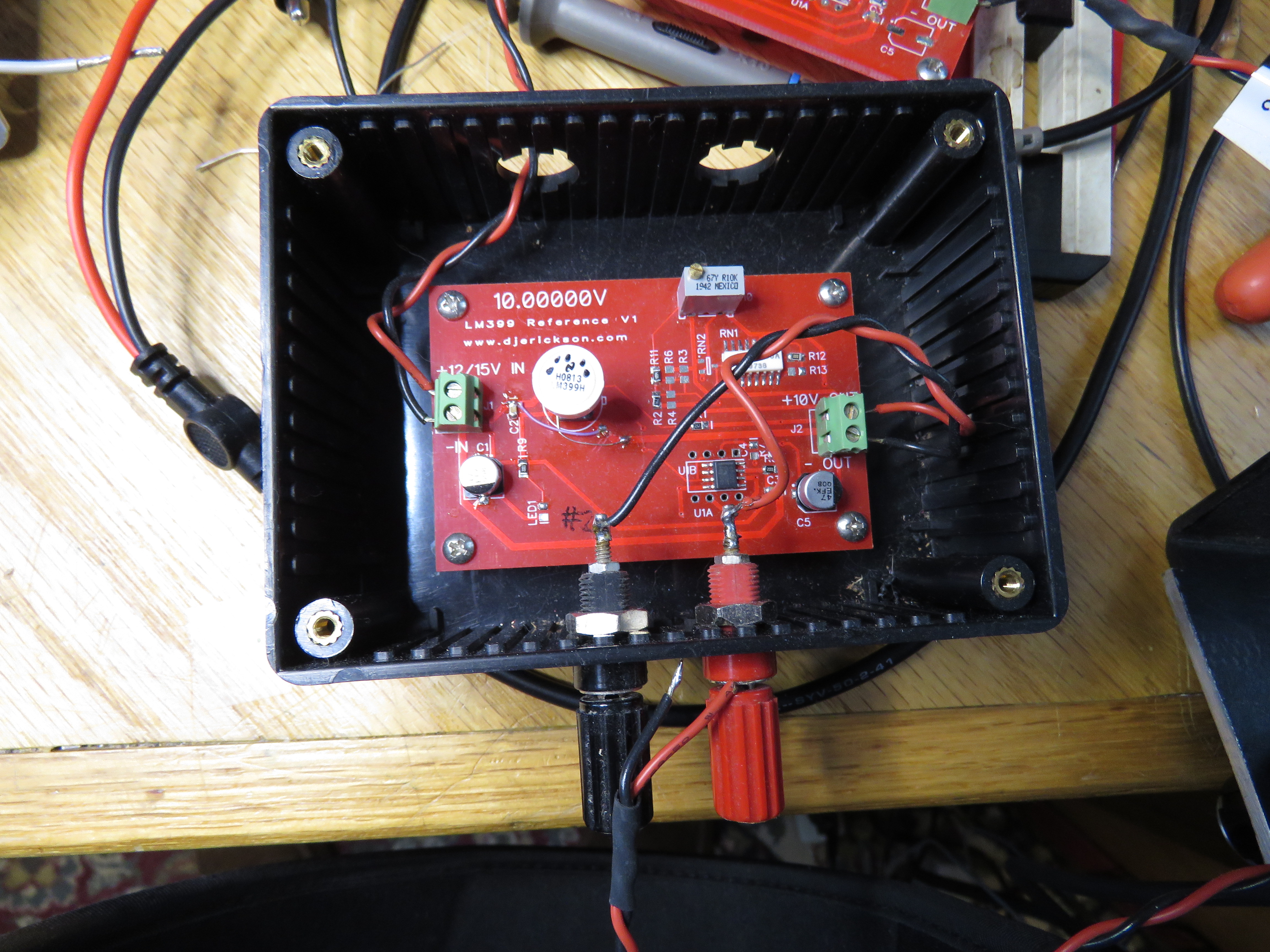
Resistor Network Version
I happen to have some surplus precision resistor
networks on hand. These are shown in the circuit below in RN1.
They are in a small SO16 package and contain two identical 6
resistor networks, each with a common pin. Each network has 2x
10,000, 2x 1,000, and one each 3,332 and 3,224 ohm
resistors. If I add a 1K to the 3332, I get a 4332 : 10K or
2.308:1 ratio. By using a 3224 instead of the 3332, I get 2.367:1.
Both of these ratios are close to the ideal 2.41:1 ratio needed to
convert 7.1V to 10V.
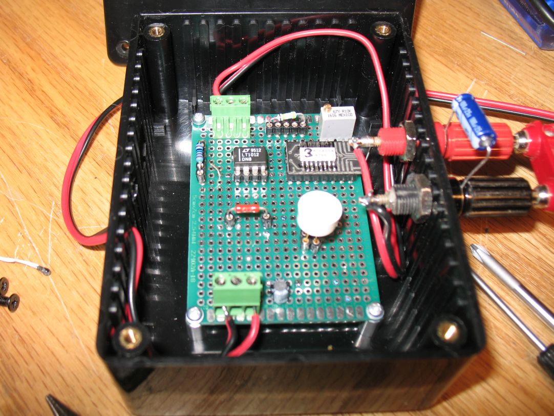
I don't have specs for these and so didn't know their tempco
match, so I soldered three parts to SO16 adapters and tested them
in a breadboard. All 3 measured about 1 ppm ratio match, which is
excellent. Here is the hand-wired prototype.
Here is a version of the LM399 circuit that uses this RN. The hard
trims R1A and R2A are still needed as is the trimpot R10.
Test Results
The first hand-wired prototype gave excellent
results. I tried several of the resistor networks and they all
provided < 1ppm/C temperature drift.
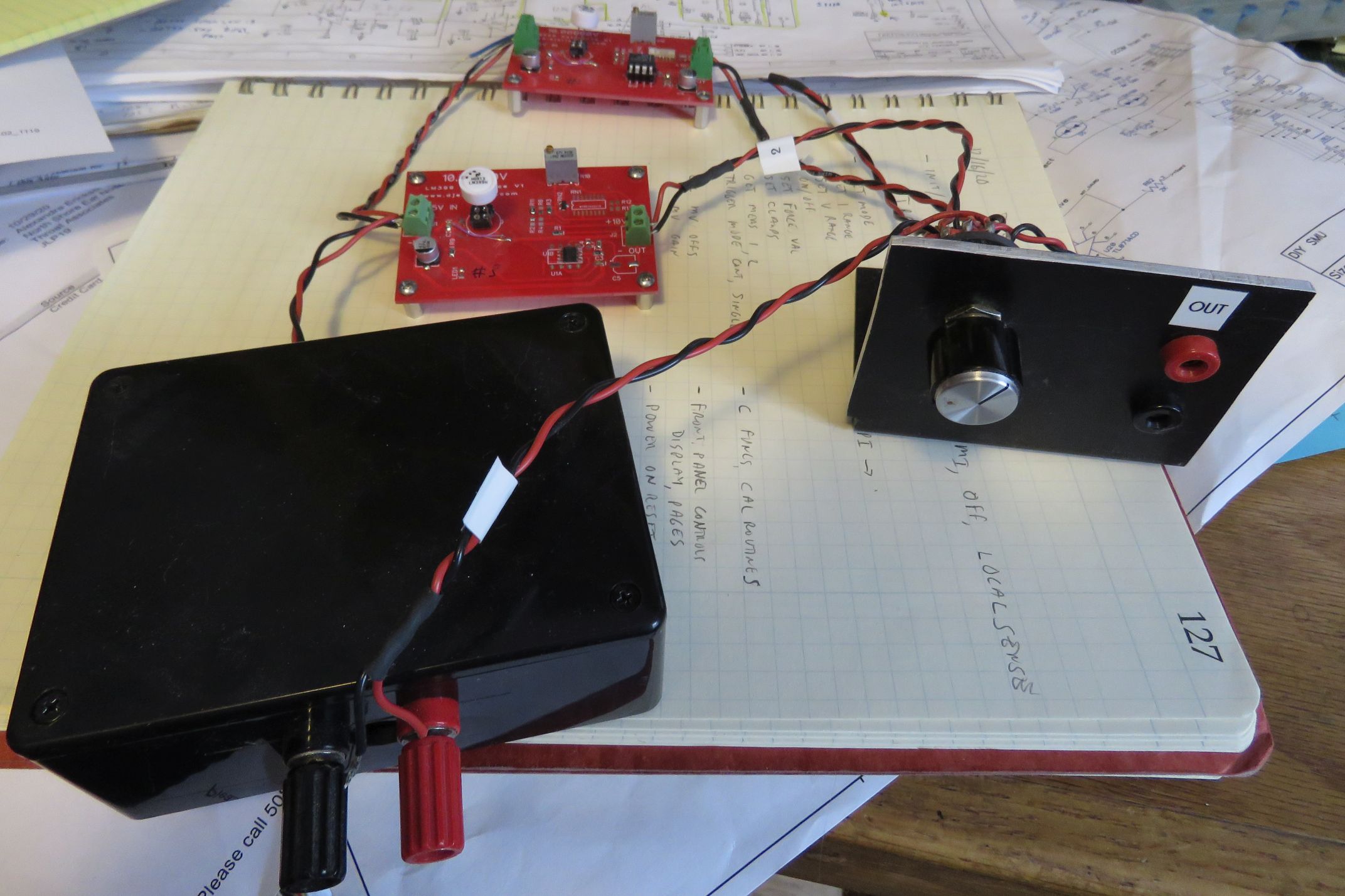
Test Fixture
To test up to 4 of these at a time, I wanted a
quick way to select them. This setup uses a 2 pole rotary switch
to select one of up to 4 boards. This
would allow the boards to be in the temperature chamber and the
selection and output jacks to be outside.