Molex K and Amp (TE) MTA Connector Page Resolving confusions
about using these very common connectors The
Blog for this project
I use a lot of Molex KK
.1" and .156" connectors. They are cheap, flexible and reliable.
Cables can be hand-built
with low cost tools.
However there are
several traps involved with these seemingly simple
connectors. There is no published 'standard' for
pin 1, Amp and Molex are almost but not quite compatible with each
other. there are gold and tin plating, which to use? Should you
use straight or right angle? Should you use crimp-and-poke or IDC
connectors? And how do you lay out PC boards for them?
Footprints
I
recently switched from ExpressPCB to DipTrace as my PCB layout
tool of choice.
ExpressPCB has common connector
footprints, but not a large selection. They do however have nice footprints
for every size
and style of Molex KK connectors. I just
used them, built lots of boards, built
lots of cables, and everything
worked out well. I also assumed
that any other CAD tool would have
these common connectors.
But DipTrace
has no Molex KK footprints or anything
looking like them. So I drew them and made them
look like the ExpressPCB
footprints.
Then
at my day job, we began
using Molex KKs with Altium
Designer. And the boards came in
backwards from the cables! When I questioned
the engineer who designed the
board and footprints,
he pointed to the Molex drawings with pin
1 on the left end. I pointed
to the Molex housing
drawings with pin 1 on the
right. For a common
part like this to
have such a trap for
designers is pretty
awful.
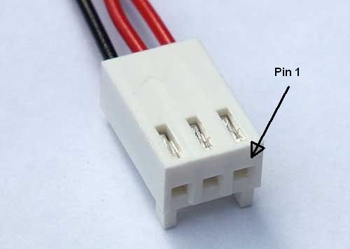
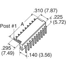
So where the hell is pin 1?
Molex puts Pin 1 of the
male header and pin one of the female housing at opposite ends!
What were they thinking?? Amp (aka Tyco, TE...) avoids the issue
by not specifying Pin 1 on the male header. But a connector is
pretty useless without knowing where pin 1 is! Additional confusion
is provided by not marking the male header with a pin 1 indication.
Come on guys!!
I, like most, use the housing standard. Of course, this confuses the PC
layout guys. But they only get confused once. Better that than
confusing the cable manufacturer forever, every time they build a
cable. If you look at DC Fan connectors which often use the 2 or 3
pin KKs, they use the housing convention.
Other Differences
between Amp and Molex.
The ramps, keys and
overall dimensions are ever so slightly different from Amp to
Molex. But Amp females plug into Molex Males and vice-versa.
However, do not try to use Molex pins in Amp housings or vice-versa. They are
quite different even if you can get the pint into the housings,
will not be reliable.
My suggestion is
to pick one manufacturer and try to stick with them. That way you only need one
type of pins and housings. I chose Molex KK a while back and have no regrets. If you must stock and use both, keep the female housings and pins
separate so you won't accidentally mix them.
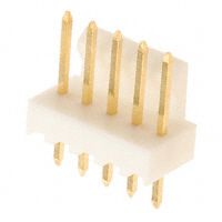
Ramps, keying, etc.
I use only male headers with the keying
feature. Life its too short to spend time figuring out how to plug
in a cable, or dealing with the smoke and damage caused by
plugging in a cable incorrectly. There is only one correct way to plug in a cable, but there are lots of incorrect ways: off by 1,
reversed, wrong plug,
The keying feature is there to prevent all of these. It has the other
advantage of preventing
you from plugging a 5 pin female into the 6 pin housing. True, you
can plug the 6 pin cable
into the 5 pin male if you're not careful, but then when
you go to plug in the 5 pin cable to the 6 pin male, you
will see the error of your ways. Hopefully before you power up the system and damage something.
I generally try not to
have two different connectors of the same size in a system. If you must have multiple
identical cables
that use the same connectors, label both the PCBs and the
cables clearly. And make sure your system will not be
damaged when
you reverse them. You will plug them in
wrong, but will eventually learn, the hard way, to
match the labels. Murphy says if someone can
build it
wrong, they will, and at the worst possible
time and with the most expensive possible
consequences.
The
females come with or without the ramps, and
with or without the keying features. I use
only ramps and keys. They look like this:
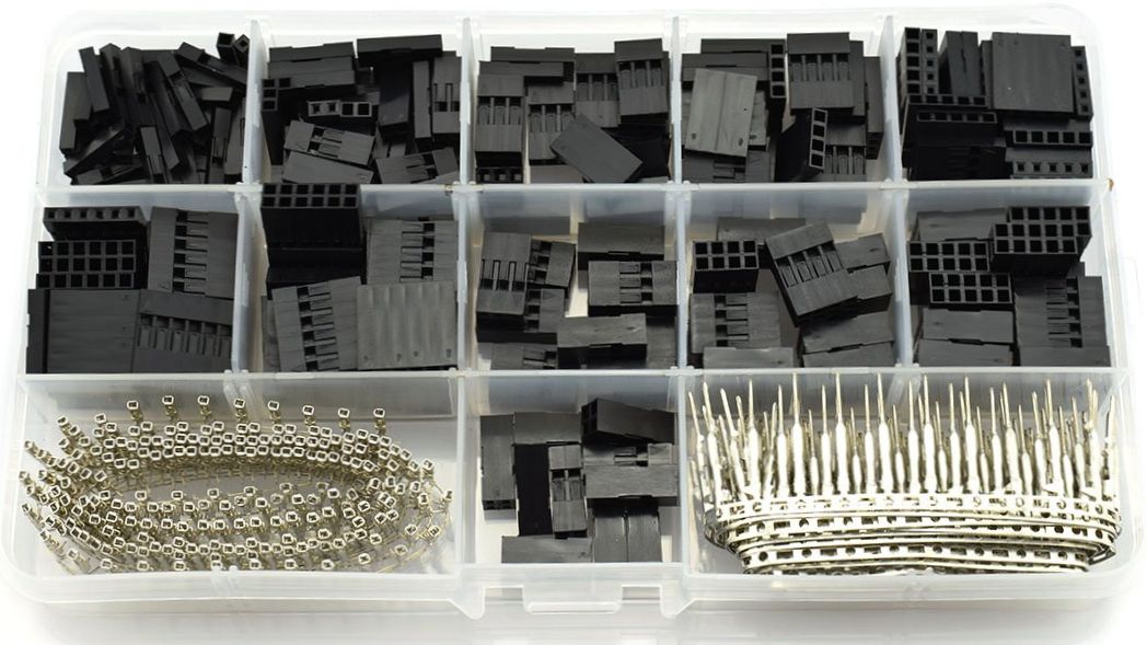
I see that a lot of makers like the Dupont
style of connectors. They have the
advantage of coming in 1 and 2 rows, and
the connectors are only 0.1" x 0.1: per
pin, no extra board space is needed
outside of the small 0.1" headers. These
are yet another type of crimp-and-poke
connector that works well. You can buy a
whole kit of these from Amazon for about
$12.
BUT
they have no keying or retention features,
so I generally avoid them. There are a few
fancier versions available with keying and
retention.
If I need a 2 row connector, I generally
use an 0.050" ribbon (crimp) type. The
cables are much easier to make:
10/14/16/20 or more connections in one
simple crimp operation. And I bite the
bullet and make toom on the PCB to
accommodate a "BOX" header for keying and
better retention.
Right angle or
straight?
Seems like a simple question, no? With a right angle
connector, it is obvious
how to mount the
connector to the board. The connector pins stick off the
edge of the board. However the straight header can be installed
with the tab at the board edge or the opposite way. My strong
suggestion it to always put the tab away from the board edge. That
way if you ever need to change to a right angle type, no problem.
Otherwise you will need to re-lay out your board to use a right angle. Now
the right angle holes should be mounted about 0.1" inward of the
edge vs. the straight, to allow the housing to sit on the board
edge. But they
can be used in a pinch,
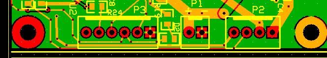
they will just stick out a bit more. Here is
an ExpressPCB
board snippet with vertical headers
aligned correctly. Note that the footprint has the tab
clearly marked and away
from the edge of the board, and pin 1 (square
pad) on the right side.
Note that if you use a right angle connector,
the tab is on the top, which corresponds to the tab on the
vertical header located away from the
board edge. Ideally it uses a
different footprint.
Cables and crimp tools
The proper ratcheting crimp tool from
either Amp (TE)
or Molex will run you several hundred dollars. I use an old Radio Shack
hand crimp tool (276-1595, $20) with good success. It works on most
medium sized pins for KK, MTA and DSUB connectors as well as most
other .1" connectors. It is fine for making a few cables. If you
are making dozens of cables,
get a ratcheting tool, and your hand will thank you. There are low cost
ratcheting tools available. If anyone knows a good
cheap one, can you post your experience in the blog?
Tin or Gold?
I design critical medical
equipment and expensive instruments. My general guideline is to use all gold plated
connectors. These resist corrosion, are more reliable,
and allow more insertion cycles. But gold connectors are more expensive than Tin. For example,
Digikey (q100) pricing for Molex KK 5 pin gold is $0.40 and Tin is $0.18. The
crimp pins are also more expensive in gold. So if your application calls for low cost
over high reliability, use Tin.
How about mixing
tin and gold? Never mix tin pins and and gold
connectors or
vice-versa. In general, dissimilar metals cause
corrosion due to electrolysis, and low reliability.
This is particularly true with gold
and tTIn. Decide whether
quality
or cost is more important on a given project,
and stick with either gold or tin.
Crimp-and-Poke or IDC?
Sorry, but there are still more choices. Both Amp and Molex make
Crimp-and-poke
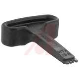
connectors. But Amp also makes IDC connectors. Some people swear by
the IDC types. You
simply push the
wire onto the back of the connector with a low cost
tool called a T-Handle. No tiny pins to handle, no
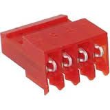
poking needed. However you will need to decide wire size
and use only one wire size for all your
connections. The color of the connector
corresponds to its wire size.
With
Crimp-and-poke, pins can be used with a range of
wire sizes. I generally use 26AWG for signals,
and 22AWG for power. One size
pin can handle 26, 24, and 22AWG. When you purchase the pins, there are yet more choices: gold or tin, wire size, single contact or
high reliability,
reel or loose.