Dave's STM32 Page
Adventures with ARM Cortex M3 processors
Including the STM32 Design Challenge Project: Multi-Zone Stereo System
The Blog for this project


I haven't done much work with microprocessors in a few years. At work we use Atmel ARM9, but my associate does most of the microprocessor hardware work. We have software professionals and tight FDA approved design control for the embedded code. My last home project was a simple RS485 network based on AVR. In the past few years I have messed a bit with Arduino, NetBurner, ExpandIO, AVR32, and others. My home projects have been mostly one-off instruments run by a PC and a USB DAQ. It is time to dig in and do some 32 bit microprocessor work with USB, modern LCDs, a real network, SD cards.

The past year (2009-10) I looked at the Atmel XMEGA. Faster, more memory, better peripherals, DMA. But the I/O structure is different enough from AVR that code rewrite of the low level stuff is needed. It's new enough that there aren't many good hardware and code examples out there. I wasn't able to find the right combination of board, debug tool, compiler and demos or examples to get me started fast. The best I came up with is AVR Dragon ($60) JTAG debugger and programmer, and Atmel Xplain ($40). IMHO, the Xplain has a bizarre combination of peripherals including audio and a 4 bit SDRAM(?!). It only brings out a few of the I/Os to connectors, and the other peripherals tie up many of the I/O pins I needed. I looked for other Xmega boards and considered laying out an ExpressPCB myself. After all this, XMEGA is still an 8 bit processor.

I suspect that Atmel is spread a bit thin with too many processor families: AVR, XMEGA, AVR32, Arm 7, 9 and M3. A bunch of other vendors have their own 32 bit solutions, but they seem to be scattered and either fully or semi proprietary. Other architectures out there: Microchip MIPS, Coldfire, lots of older ARM7 and ARM9, TI's OMAP (high end).

Recently eight or more IC vendors have adopted ARM Cortex M3: NXP, Atmel, ST, TI, Toshiba and others. The architecture has caught on for good reason. It is open, the variable-width Thumb instruction set is efficient, processors exceed one instruction per clock cycle. Fast, hardware multiply and divide, low power, low cost, open tools,  a wide range of devices, lots of nice peripherals including DMA, high-everything-good, low-everything-bad.... ARM Cortex M3 looks like the best upgrade for an 8 bit architecture.
discovery
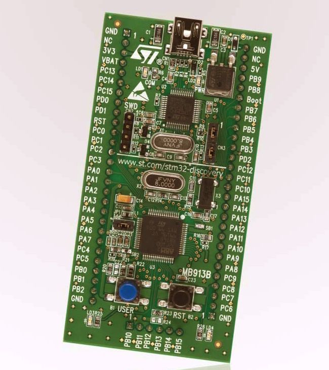
A friend returned from the 2010 Boston Embedded Systems Conference with a couple of STM32 Discovery modules (photo thanks to ST). Originally I used Atollic TrueStudio software (lite version, nearly full functionality) and tried a few of the examples. Atollic is gcc and Eclipse based (good and good), and supports full source level debug (nice). But Atollic is now code-size limited to 32K for the free version. I have since switched to CooCox development environment. Like Atollic, it uses gcc and Eclipse, but unlike Atollic it is free and not limited in any way. Also CooCox supports hundreds of ARM CPU variants from nine different manufacturers and with many different debug interfaces.

I looked at the Discovery hardware: STM32F100RB processor, 24MHz ARM Cortex M3, 128K Flash, 8K RAM, gobs of I/O including 12 bit ADC and DACs. It has a 2-wire debug (SWD) to save pins (vs. 4+ wires for JTAG). The Discovery module is a decent form factor that brings out every processor I/O on a convenient DIP format. Then I looked up the Discovery module price: $10! OK, now I'm very interested.

This is an amazing deal compared even to the low-priced Arduino ($30) or anything that Atmel or Microchip offer. It beats mBed and other CortexM3's for cost of entry. I suspect the modules are built at a loss by ST, but we might as well enjoy them while they last. In fact, ST doesn't allow you to use the Discovery modules as part of a commercial product, you can use it only for development and one-offs.

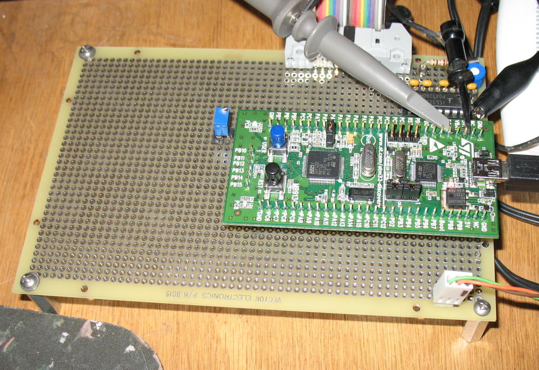
The core processor consists of only an STM32F100RB plus 2 crystals. The only on-board I/O is 2 LEDs and a push button. Perfect: their stuff won't get in the way of your application. The current Digikey price for the processor IC is $3.50, qty100. The board also contains another smaller STM32 with USB, factory programmed as the debug interface. The two-wire SWD debug interface is brought out to a 4 pin connector, allowing a Discovery to be used as a debug interface for other STM32 designs.

If that isn't enough, just for signing up for the new STM32 design contest, I received a Discovery module with the STM32F103 chip for free. Same board, but the processor has 1MB of flash, 96K RAM, 72MHz and even more I/O. There are STM Discovery modules for the F0, F100, F200, F300 and F400 families. All for under $15. Modules for the larger pin devices use dual row headers.
STM32 I/O Ports
Arm I/O ports are considerably more capable than old 8 bit processor I/O.   The old style generally consisted of an output port register, a pin read port, and a port direction register, all 8 bits. Some ICs have open-drain mode or other features.

The STM32 and most ARM processors have 16 bit ports, and each port has ODR (output data register), IDR (read pin register) and Direction, but the ODR and the direction registers each have separate Bit-Set  and Bit-Clear registers. Why is this important? With the old ports, to set one or more bits required one to do a read/modify/write (R/M/W) cycle to the port. Simple enough, but this creates a problem when a main routine, several interrupt routines and and DMA all try to operate on different bits in the same register. The contents of the register can be corrupted if one routines R/M/W cycle is interrupted by another routine trying to set other bits in the same register. A separate flag or other mechanism must be used to prevent this. It gets worse with 16 bit GPIO registers since it is more likely that multiple device handlers will want to access different bits in the same I/O port. And worse again with DMA. The solution is to use the separate bit set and bit clear registers. These do not require R/M/W cycles. They are faster, too.

BTW the same is true of any peripheral on any processor and always requires programmer awareness and care. If the main routine wants to read an ADC channel and an interrupt routine or DMA channel wants to read another channel of the same ADC, the state of the peripheral will be corrupted. For the ADC, The STM32 and most other ARM3 processors have a separate set of registers to permit this possibility.

1/12/2011
I am looking for a good blog about STM32.   http://www.stm32circle.com/forum/index.php looks like the only active one around. UPDATE: CooCox has a very good forum.

On the original Discovery I have a test program running with basic ADC, DACs (using DMA), USART / sprintf() and GPIO. It is a combo of some of the STM32 demos. I separated out the demo board specific code since the Discovery code didn't provide much interesting stuff. I'm willing to share my code. Let me know if you would like it.

Next is to get an alphanumeric LCD, and a 128x64 LCD working, using GPIOs for the 8 bit bus plus the control lines.  breadboard

Here is the discovery module mounted to a 4" x 6" proto-board from Vector. The colored ribbon cable connects to the LCD. In retrospect I should have just mounted the LCD on the empty part of the board. It can be mounted straight or right-angled using a simple .1" right angle header header.

I'm planning to write a simple ADC routine, getAdc(chan), using programmed I/O only (no interrupts or DMA). Has anyone written this yet? It's a bit tricky because the ADC is designed to measure a list of channels, but there is just one register to deposit the result. This works fine with DMA or a fast interrupt. My plan is to ADC a 'list' of just one channel.

1/18/2011
I spent too much time last weekend looking for LCDs for the house-wide audio project. It was a slog opening and reading dozens of data sheets. What I am looking for is a simple low cost, lo-res monochrome display to display text, and simple graphics. I have old C libraries from my FPGA controllers on BoatBus, but my old controllers were overly complicated and were not 3.3V compatible. They required an FPGA/CPLD plus a RAM, plus DC-DC converter... Too much like work. All I ask of an LCD is:
Unfortunately the older / surplus LCDs are mostly low contrast, green or yellow LEDs or worse, electro-luminescent, and 5V only devices The old Samsung KS108 controllers require 5V logic. I have a few of these panels lying around. The newer 3.3V displays are mostly Chip-on-glass (COG) and require high pinout (40-50 pin) fine pitch connectors and a bunch of external capacitors for the DC-DC. NewHaven Displays seems to have the displays I want and their products are in stock at Digikey and Mouser as well as others.  I like the NHD-12864WG-BTFH-V#N. This part uses 5V power, and the Vih (Input Voltage high) spec is 2.0V, so 3.3V logic is OK. The Voh spec is 2.4V at low current. These are TTL compatible specs which are 3.3V / 5V tolerant compatible. Unloaded, the outputs will go to to 5V, but since STM32s I/Os are 5V tolerant, life is good. If you are using a non-5V-tolerant chip, you may be able to use series resistors and Schottky diodes to +3.3V on the 8 bit data bus to protect the CPU inputs. Or some other 3/5V translation trick.

2/12/2011 LCD Working
After a few weeks, I have the 128x64 LCD code working nicely. Low level reads and writes to the LCD,  5x7 font and lcd_string(), putpix, linedraw and ellipse drawing are all working. See the LCD page for the details and to download the current code.

lcd working

3/21/2011 STM32 Design Deadline
The STM32 design contest deadline was extended a week to Monday 3/21. This was just enough time to allow me to sprint to the finish. On the previous weekend I finished the 2 board designs: the crosspoint and quad preamp boards. On Monday 3/14 I ordered the 2 boards and the parts. On Thursday and Friday, the boards and parts arrived and a soldering frenzy ensued, followed by a coding frenzy over the weekend of the 19th.
See the Multi-Zone Preamp Page for details.

12/26/2013 New STM32F103 project
I began a new STM32 project, this time it is commercial. The design uses the STM32F103VC processor. 100 pins, 72MHz clock, internal USB. For development I used the $20 ST-LINK/v2 from ST. To get the basic code and development tools working, I connected the ST-Link to the new prototype board. changed the processor type in CooCox. It was a simple matter of  re-compiling (no errors!) , loading, and running running my old MultiZone code with no changes! And it just loaded and ran! Of course when it tried to access the non-existent I2C peripherals, the code hung waiting for an acknowledge, as it should.

When I connected a PC serial port to USB cable to UART1 Tx and Rx, it was communicating at 115.2K baud. The ST libraries calculated the baud rate based on the new processor clock. When I disabled all the I2C peripherals, the menu system came up. Yay! The new board has many SPI peripherals, unlike the MultiZone with its many I2C peripherals. New challenges....

STM32 Documents
The STM32 Processor Reference Manual RM0041 for the STM32F100xx family details all the I/O, memory, and debug devices. Very well organized, this is the STM32 F100 bible.
The Discovery UM0919 User Manual has the pinouts and schematic for the Discovery Module.


The Blog for this project
Multi-Zone Preamp Page
LCD 128x64 Page

Last Updated: 3/2/2013