Sure,
there is open software out there. Linux comes to mind. And there are
even
a few open hardware projects. This is intended to be a completely open
embedded system. Schematics, source code, and PC layouts are all
available
for you to look at, use and possibly contribute to. Most businesses
need
to keep designs proprietary in order to maintain a competitive
advantage.
This is not a company, it's a part-time endeavor and I am doing it
purely
for my own enjoyment. And I wish to share it with other people.
What
BoatBus is in the most general terms, is a system for collecting data
from
the environment, and displaying it for humans to read. It Also allows
the
human to control some aspects of the environment. The first system is
intended
for both home and boat use. Common functions between a home and a boat:
collecting weather and environmental data, power usage, controlling
lights
and sound, displaying in several convenient locations.
I'm
Dave Erickson, an EE. I've worked at several companies in the Boston
Route
128 area since graduating WPI in 1976. Two years at HP medical, then
three
at a startup: Octek, where I was half of their consulting group, and
where
we
designed just about anything for just about anyone. Then Datacube as
Director
Engineering for 15 years, doing real-time Image processing. Then
4.5 at Analogic
as Chief Engineer of the Test and Measurement division. Then to Zoll
Medical, working on Defibrillators, then a startup stint and curently
at Teradyne, where we make big ATE machines. My skills are mostly
analog
and digital hardware design, but along the way I began doing assembly
programming, and then C. At home, I build electronics for home
and
boat. I like to mix analog and digital hardware design and software in
a complete system with sensors, data acquisition, processing, display
and
a bit of communications thrown in.
For
the past few years I've been working on a networked display and
data
acquisition system. I did the first generation of a similar system
about
10 years ago. It used a surplus LCD panel, a 68hc11 micro, and a bunch
of code and custom hardware. It was a single box system designed to
provide
my boat with a bunch of marine-type data: wind speed and direction,
boat
speed and direction. It also provided rudimentary navigation by
maintaining
a dead-reckoning track.
Since
then, LCDs and FPGAs have gotten a bit better, processors are faster
and
more integrated, and C tools have gotten a bit better. I decided to
network
this system in order to support remote data acquisition and display.
Meanwhile
chips have gotten smaller, requiring more advanced prototyping
techniques.
But the good news is that companies like expressPCB now offer decent PC
boards at prices hobbyists can afford. Their Mini Board service is
three
2.5 X 3.8" boards for $51 plus $10 shipping, delivered in less than a
week.
And the CAD tool is free also.
BoatBus
I
The
name BoatBus is my generic name for my old boat project, BoatBus.
While
it worked OK, it was really a functioning prototype, and had some
limitations. In reality it was not a bus. It consisted of a
single
box containing all the signal conditioning, acquisition, processing,
and display circuitry.
This made it larger than I'd like a display to be. It also meant that
all
the low level analog sensors had to be wired directly to the main box.
I used the system for two years aboard my old boat. When I moved to a
newer,
larger boat, I never installed it. It's size was inconvenient and not
really
worth the hassle to wire it all up. Plus, GPS now offered most of
the nav features that BoatBus had. Also it had no expandability: to add
a new sensor or
a second display required significant re-engineering. But it was a good
first step towards the ultimate system.
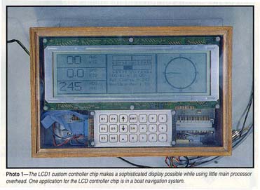
 The
old surplus LCD display was a Hitachi HD215XP. It was not backlit, and
had the annoying habit of completely blacking out in the heat of direct
sunlight. I learned not to use a first generation LCD outdoors. Also
the
form factor required a large enclosure, and there is no room for large
boxes in the cockpit of most boats.
The
old surplus LCD display was a Hitachi HD215XP. It was not backlit, and
had the annoying habit of completely blacking out in the heat of direct
sunlight. I learned not to use a first generation LCD outdoors. Also
the
form factor required a large enclosure, and there is no room for large
boxes in the cockpit of most boats.
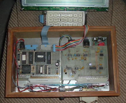
Here
are the innards: the 68hc11 processor board on the left with the
original Actel LCD1 controller. The analog board is the real PC board
on the right. I used 96 pin DIN connectors to connect them together.
Tucked in the upper right corner is a the +5V switching power supply
which is a National evaluation board. The entire system drew about 120
mA current from +12V
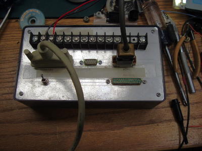 The +12V
power and the sensor wiring comes from the 25 pin D cable on the lower
right. It connects to this breakout box with connectors for the various
sensors
The +12V
power and the sensor wiring comes from the 25 pin D cable on the lower
right. It connects to this breakout box with connectors for the various
sensors
I
decided
I'd also like LCD displays at home, to display weather, house power
use,
and to control my house-wide stereo system. I began a wish list of
features
for the boat and for the home.
Better,
more readable display with backlight.
Faster
processor to allow faster displays without programing tricks
A low
cost serial bus to communicate data
Ability
to use multiple displays and sensor modules
BoatBus
2 Overview
The
decisions of what
type of displays, how to architect the communications, what processor,
tools, etc are all journaled in these pages. Here is an overview of the
system designed to meet the above goals.
The
system consists of nodes connected via an RS485 network (bus). The
bus consists of four wires that are daisy-chained to each node. The
wires are: D+, D-, GND and +12V. That way each node can be powered off
the network, assuming it doesn't draw more than a few hundred mA. All
the network requires other than nodes and wiring is a 12V power supply
at about 1-2A. For home, a small switching supply provides it. For the
boat or for automotive applications, it can run directly off the
+12V battery source with minimal conditioning. The wiring is
simple CAT-5 twisted pair which provides 4 extra wires. It uses
simple screw terminals so the system can be easily field wired with
just a screwdriver.
Nodes
can be or do just about anything, but for now I have designed two
types: the first type is display nodes. These generally collect data
off the bus (recieve) and display it on a graphics LCD. The other types
are data collection nodes. These interface to sensors, make
measurements, and send the data to the bus. Any node can either recieve
or send, or do both.
This
sounds simple enough, but most of the RS485 'protocols' in the
world are Master (typically a PC) -centric. A PC masters the network,
collects data from numerous slave nodes, and then displays or stores
the data. I wanted to eliminate the concept of a single point to
collect the data, and definitely eliminate the PC. In a boat or a
house, one may want multiple displays. Using most protocols, the master
PC polls each node, collects the data and then sends it to the displays
if there are more than one. This seems wasteful since data then is on
the bus twice. I wanted a more democratic system where each node can
send data if it has some to send, and each display can recieve it and
display it if it wants the data. A broadcast system. Any RS485 network
does need a way to coordinate traffic and eliminate collisions,
so some bus timer (master) is needed, but it can be merely a traffic
cop. It doesn't need to process the data, just say who's turn it is to
go next.
Dave's
rule # 7: Before you build something for the boat, build one for home
or for the car. Much easier to get the bugs out when not surrounded by
salt water. I have played with home control and weather stations
in
the past. I could see
the value in having a few displays and control
panels around the house.
The
details on the communications protocol can be found here.
The decision of
which processor to
use is here.
Discussion of graphics LCDs is here.
The first node, used to collect weather sensor data for boat and home
is here.
BoatBus
2 Display
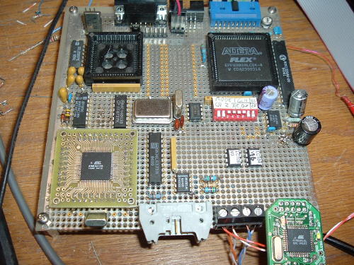
Here
is the hardware for the display node. I needed something to show for
the
effort and thought so far, so I installed the prototype hardware
in an enclosure, along with a QVGA LCD panel. Here is the proto of
the AVR Mega128 processor with an LC10X
type LCD
controller. The empty sockets on the top left are from the old 68hc11, SRAM and EPROM that I
removed. The Mega128 is on a prototype adapter from http://www.devrs.com/store. In the upper right
are the LCD controller FPGA, 8 pin config EEPROM, and display RAM
. The IC and caps on the right are the V- power supply for the LCD.
JTAG ICECube for development is lower right.
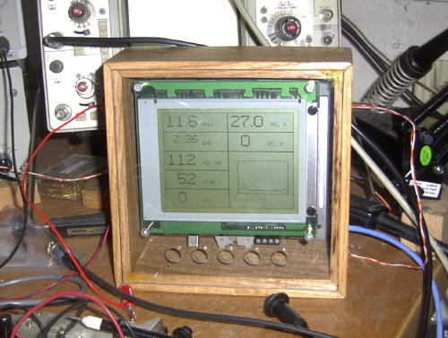
 Here
it is with the above controller board mounted behind the QVGA LCD in an
oak enclosure,
and nearly ready to install in the kItchen. The overlay and buttons are
missing. The holes below the display are for 5 push buttons to control
the display. Someday.... Meanwhile this display provides me and my
family with the outdoor temperature and wind speed / direction, and a
display and plot of our home energy use.
Here
it is with the above controller board mounted behind the QVGA LCD in an
oak enclosure,
and nearly ready to install in the kItchen. The overlay and buttons are
missing. The holes below the display are for 5 push buttons to control
the display. Someday.... Meanwhile this display provides me and my
family with the outdoor temperature and wind speed / direction, and a
display and plot of our home energy use.