- Use a 'solder-less proto board'
- Build a prototype PC board
- Build a hand-soldered prototype
- Build a wire-wrap prototype
Hand
wired proto-boards.
When
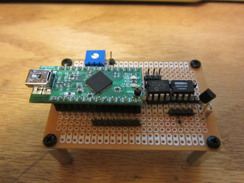
I need a quick and simple prototype with a few ICs, I often use the Radio Shack proto boards.
These work great, cost only a few dollars, and are available at the local mall.
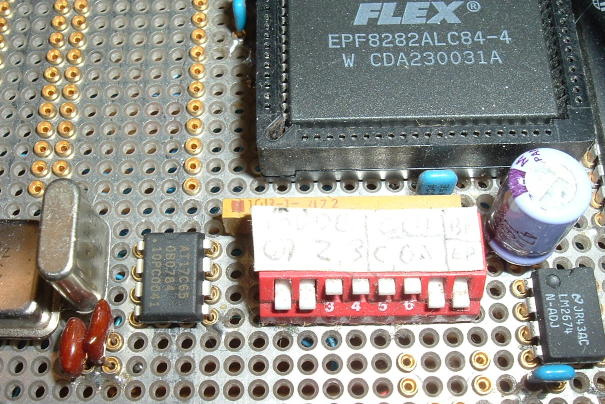
The PC pattern has two bussed power signals
and is set up for DIP
ICs. I always socket ICs and
sometimes the discrete components as
well. Here is a prototype using a FTDI
USB module. For wire I use
wire-wrap solid 30AWG. An advantage of this method is
the low profile: no long
wire-wrap pins on the back
side. For SMT parts I buy DIP
adapters from Aries
and other companies.
Radio
Shack builds a larger
version. Another approach
is to
use a 0.1" grid
board with either
single sided or
double sided
pads. Buy these
in
large
sizes and you
can cut
them to the
exact size you
need.
ExpressPCB
When
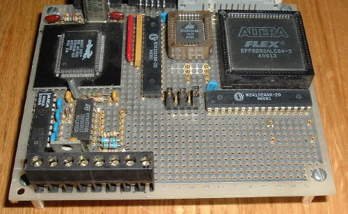
I need more than one of something, I like to use ExpressPCB. These
folks offer a
'Mini board' service of three 2.5" x 3.8" double
sided boards for
$59. Larger boards are a bit more expensive. 4 day
delivery,
features as small as 7 mils, no solder mask or silk
screen. .Their
schematic and PC layout software is very easy to learn and
quite good
quality. At work I use them for just about all
prototyping,
building test boards, SMT adapters, etc. Check out the WeatherNode page for an example.
I tend to use
surface mount for these small boards since I can fit more
circuitry
that way.
ExpressPCB has improved over the years.
They support 14 mil vias, filled planes, and 4 layers. 4
layer boards support 8 mil vias.
For an extra $24,
you can get silk screen and solder
mask on your Mini Boards. This
makes boards easier to
assemble and much more
profession looking. I
usually get this service. The next
service up, ProtoPro, costs $166 and you get four
boards of any size
up to 21 sq in.
This allows you
to build any size boards. If
you need smaller boards, you
can palletize several boards
or several small designs
on a single 21 sq in
format, then when you receive
them, saw the boards apart.
Back
to wire-wrapping
For more complex boards,
I use wire-wrapping. Wire-wrapping
does require good tools and supplies, and care when
building stuff.
Wire-wrap's
perceived problems:
- Inadequate grounding and power distribution for high speed, power, or analog designs.
- Un-reliability
- Hard to build and maintain.
- Too much work
The grounding and power distribution can be close to the performance of a multi-layer board. The signals (if scatter wired) don't cross-talk as much as PC boards, with their close, parallel traces, and the reliability, if done right, is excellent. Early satellites and manned space vehicles used wire-wrap.
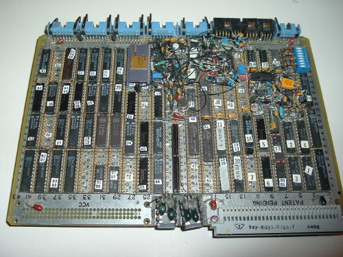
For grounding and power distribution, I generally use double plane (ground and power) vector board. I prefer the Vector Power/Ground plane board with the 0.055" holes. This board has uncommitted holes on 0.1" centers everywhere but the edges. It is available in different standard bus form factors: AT-Bus, Eurocard, etc. It is low in cost because it has no plated through holes. All holes are clearance holes through the planes. All holes are 55 mil and accept press-fit, machined-contact pins.
I buy the larger Vector boards (cheaper per square inch) such as E220-6U-3, which is a 6U VME board, 160 x 220mm, for about $27. Cut them to the size you want with a hacksaw. If you cut along a row of holes, the hacksaw will tend to follow the holes and cut nice and straight. File the edges smooth. Drill 1/8" mounting holes for #4 screws and spacers. Trim the power plane away from around the mounting holes if you plan to use metal hardware. In this way, you can build a board of any size or shape. A good rule in electronics packaging is to make the board fit the box since it's generally easier to make a custom shape board than a custom shape box. Get the box first.
For pins, I use the Vector T31 (or equivalent) machined contact wire-wrap pins. These provide excellent IC socket connections. They are pressed into the board in only the required locations, using a snap-action punch tool, with bit.
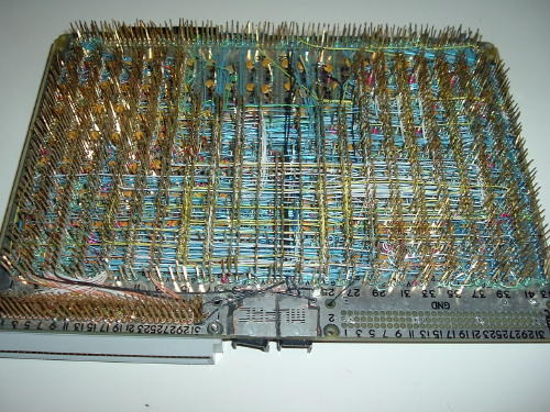
The pins are generally gold plated, and not cheap. If you buy 100 from Digikey, they will cost you $.27 each, meaning that a 20 pin DIP costs 20 X $.27 or $5.40. An 84PLCC costs $22.68. Ouch! But I have found a virtually unlimited supply of these pins for dirt-cheap. Older DIP wire-wrap boards by Augat and Mupac used them by the thousands. I have scrounged several used and unused boards. Unused boards are more desirable; with used boards, you need to unwrap the wires first, which is time consuming. With a new or partially unused board, each pin can be removed in about 2 seconds time. I use an old wire-wrap bit epoxied into a hole in the end of a piece of broom handle, as shown below. Place this over the back of the pin, and push. The pin pops out nice and clean. In one episode of Law and Order, at 2 seconds per pin, you just saved $486.00 worth of pins. I leave the soldered-in power pins, if there are any. But if you remove the solder with with solder-wick, these too can be salvaged.
To find these boards, search Ebay for Augat or Mupac. The 1/16" (0.062") thick boards are what I prefer. I tried to extract pins from some Augat 1/8" (0.125") boards and was not able to because the shoulder on the pins does not protrude far enough through the board. 1/8" boards from Mupac tend to use pins with a longer shoulder, and are fine. If you find a way to get pins out of the Augat 1/8" boards, I'd love to hear it.
If you find these boards, you can also just use them as-is, assuming your packages are all DIPs. I haven't built an all-DIP board in years. There's always one or more PLCCs, QFPs or some other non-DIP parts on my boards. So I use new vector boards with full 0.1" grid.
Then press in the pins in to achieve the placement you want. The next step is to solder the power and ground pins directly to the ground and power planes. I generally put the ground plane on the top, just in case I drop a wire or scope probe ground onto it. So the power plane is on the bottom. With careful soldering, you can connect the pins to the appropriate planes.
Any extra solder, mistakes, or shorts can be fixed nicely with Solder-wick. Care when soldering on the top plane is required to prevent getting solder in the socket hole. If you do, the pin is trashed and should be replaced: wick out the solder and push the pin out.
You
can isolate parts of the top or bottom planes by cutting
them with an
exacto
knife.
The Vector grid board also has dedicated connector area for 0.1" headers and for D connectors. These can come in handy. I try to make sure there are a couple of ground pins on each end of each connector I mount, just for mechanical strength. With grid board that uses plated-thru holes, you can solder connectors anywhere.
Unless you have dedicated D connector footprints on the board, it's easier (and much smaller) to mount a 3 pin or 10 pin header to the board, and then use a ribbon cable or discrete wires to adapt the header to the 9 pin or 25 pin D, which can then mount on a panel. If you only need 3 wire serial ports (TX, RX and GND) then you can use a small 3 pin header and a discrete wire connector to the D.
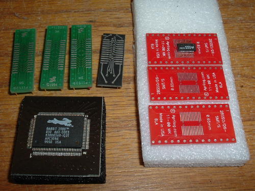
For
most ICS I use DIPs if they're available. Many chips are.
If not, I use
SMT adapters. I use 0.050 pitch SOIC adapters that will
take up to a 24
pin device. For smaller 50 mil pitch devices, I cut the
adapter down to
size. That way one adapter size fits all. I also have some
25 mil SSOP
adapters. For something really crazy you could build
a custom
adapter
board for one or more ICs using expresspcb.com for only
$51 for three.
For PLCCs, I use PLCC sockets, plugged into the machined contact pins. Make sure your PLCC sockets have thin enough pins to work with the machine contact wire-wrap pins.
For QFPs, I buy adapters from Aries, Augat, Winslow, etc. There are tons of types of adapters available. Some are pretty expensive, like $30 for a 100QFP adapter. I recently found a neat adapter that will take any size QFP in either 0.8mm (up to 80) or 0.5mm pitch (up to 100). http://www.devrs.com/store. It came without pins, so I used some thin ones so I could socket the device. You can also just use 025" single or double row headers and wire-wrap directly to it.
For discrete components, as long as the lead diameter is under 0.020", they can be pushed into the machine contact pins. When pushing 1/4 W resistor leads in, the leads are a little thick, so hold them in needle-nose pliers and push straight in. They tend to bend. Practice makes perfect. Ceramic Caps and 1/8W resistors are fine. It's nice to have all your discretes socketed in case a design change is necessary. For parts with thicker leads, mount them to DIP carriers, or solder on thinner leads. Or mount them right to the board without pins. Or you can solder them into the pins.
For high-frequency bypass caps, I solder 0.1uF radial lead ceramic caps, mounted on the back of the board, to the power and ground planes under each chip. Use very short leads. Because of this and the use of planes, the power distribution is quite good, even at high frequencies. Wire-wrapping the caps will add inductance and decreases the cap's high frequency effectiveness.
Mount the caps first, because soldering after wire-wrapping is hard to do without melting wire insulation. But it can be done, if you're careful.
Wire-Wrap all the connections. Work from a schematic and mark off the connections as you make them. (I never do this). I prefer pre-cut and stripped wires. After you un-wrap a wire, don't re-use it (Do what I say, not what I do.)
For super-critical stuff where you're worried about the wire-wrap pins inductance, or the wire inductance, you can cut most of the pin off, and solder wire or components to the stubs. I've wire-wrapped all kinds of line-level audio, ECL up to 125 MHz, and just about everything else.
With adapters, PC boards, headers, IC sockets and various connectors, I sometimes buy the longer ones or larger ones, then cut them down. I use tons of 10-20 pin connectors such as dual row RA headers, and as a result have scads of 26-50 pin ones unused and taking up space in my bins. So I'll cut down the longer ones to make short ones when I need them. You can get 3 or 4 10 pin headers out of one 50 pin header. The crimp-on ribbon cable connectors can also be cut, but only in a pinch since you lose support for one end. Cut with a sharp pair of dikes or a hacksaw with a fine blade, then file the edges smooth. Works for PC board also. If you're careful, you can even cut multilayer board. If you file the edges nice and smooth, the inner layers and planes won't short.
Tools:
Wire-Wrap gun: hand or electric with 30 Ga bit and sleeve.
(Ebay)
Hand insertion punch tool for pins, Vector P158V or equiv.
Die Adapter for Vector R31 pins: Vector D10
Pre-Cut Kynar wire-wrap wire,30 GA. I prefer blue.
Google for
suppliers.
Kynar Wire-wrap wire,30 GA, various colors
Teflon Wire-Wrap wire (good for soldering)
Wire Stripper. I use OK AC powered gun
Hand un-wrap tool
Block of wood with spacer: backing for punch
Tweezers
Needle-nose pliers
Diagonal cutters, fine
Dave's pin remover (see photo)
Vector Grid board with 2 planes and 0.055 holes
Vector T21 or similar pins
Temp controlled soldering gun with various sized tips
Solder-Wick, various sizes,
Rosin core solder, 0.020 and other sizes
Solder Sucker
Various single and dual row headers
Various connectors
Get your wire-wrap gun on Ebay for < $50. There are a handful listed as I write this. Search for Gardner-Denver or OK. Get a good one. Battery or AC are fine. The battery ones are heavier. Make sure there's a clutch so the wire part of the bit is always facing up. Otherwise you spend time searching for the teeny hole for the teeny wire.
Vector has gone way up on the staking tool price. Get a generic staking tool from somewhere else, and just buy the Die from Vector. It just screws into most staking tools.Digikey has most of the Vector products: tools, board, pins, etc..
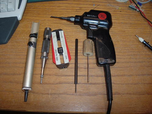
In
this photo (R-L)
1)
A decent solder sucker
2)
The Vector pin staking tool
3)
30 GA wire wrap wire stripper
4)
Hand un-wrap tool
5)
WW pin removal tool (homemade)
6)
WW gun
LAB
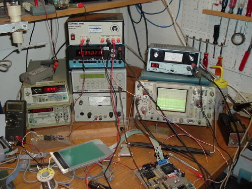
Jim Williams from Linear Technology believes having a good home lab is a great thing an EE can do for a career. It allows you to build and test circuits quickly and easily. My original lab is set up in a corner of the basement. I built one wall to separate the electronics from the wood shop and try to keep the dust down. In the summer it's nice and cool. In the winter, it gets chilly so I turn on a space heater.
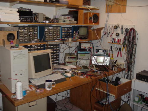
For equipment, I have scrounged, bought and pulled stuff out of the scrap heap. Most companies no longer repair broken equipment. I love to. For example, my boss, Stan at Datacube sold me a broken Tek 465 scope for $10. That evening I found the bad 741 op-amp in the power section and replaced it (socketed) in 15 minutes. Scope has worked swell since. The PowerMate power supply was pulled out of the trash and repaired in an hour. The big HP supply was on the equipment shelf at work with a mashed front panel, no mounting for the meter, and a "do not use" sticker. I asked if it was available and the lab manager said "take it". It took two hours to repair at home. The DP3600 DMM: Ebay for $40. It was flaky, but in an evening I found the intermittent relays, cleaned and adjusted the contacts and now it's fine.
If
you're just getting started, one way is to get a powered
solderless
breadboard.
Mine has three supplies, switches and pots, etc. You'll
need a scope
and
handheld DMM.
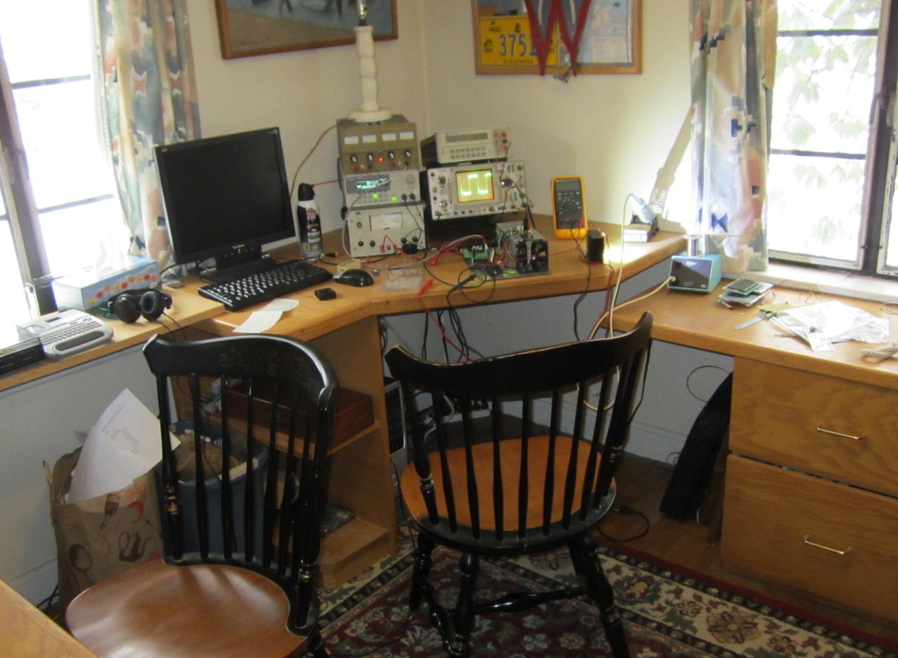
My latest lab is now upstairs. Our daughter has her own place, so we are now empty-nesters. This freed up half of a coveted upstairs room in our small house so I moved my main lab upstairs. Central heating and natural lighting are beautiful things. Here is the new lab:
Test Equipment:
Scope:
Tek 2445, 150MHz dual channel
Scope:
Tek
465, 100MHz dual channel
Handheld
DMM Fluke 87-III
Handheld
DMM Data Precision DP945, 4 1/2 digits
Bench
DMM Data Precision 3600 5 1/2 digits, 2/4 wire Ohms,
(from Ebay)
Bench
DMM HP 3478A 5 1/2 digits, GPIB.
Nice
Fluke
8920A True RMS DVM
Fluke
7260A Universal Counter, 100MHZ
HP 33220A Arbitrary
Waveform Generator, 20MHz
Analogic 620: sine to 10MHz
Audio
Distortion Analyzer, homebrew
Data
Acquisition:
NI USB-6009 14
bit
Measurement Computing
USB-1608FS 16 bit
Power
Supplies:
HP
6286A, 20V, 10A
Lambda LPD-421A-FM 2 channel 20V 2A
Homebrew VI
Voltage current source.
Power
Mate Corp. BPA-40C 40V, 0.5A, pulled from the trash
and repaired
Various
switching and linear open-frame supplies
Microscope, stereo low cost AmScope (Amazon.com)
Homebrew Electronic Load, constant current, 50V, 10A max.
Lots of cables, test leads, and adapters many homemade.
Development
tools:
Altera USB Blaster download cable
Atmel
AVR ISP download cable ($29)
AVR
JTAG ICE Cube ($39)
Various
serial and parallel cables
GAL
programmer, homebrew
Parts:
I
have obtained many parts as samples. Mostly the
manufacturers give them
away in hope that you will design them into your product..
Some were
leftovers from work projects. Also companies
scrap tons of parts, and I'm not too proud to go
through the
trash,
or pick out a few useful pieces before the scrap dealer
gets
there.
I have a pretty full assortment of linear and digital
parts, collected
since the seventies. I keep most of the parts in bins, but
not the
linear
ICs. These I keep on black foam, organized by
manufacturer. For surface
mount ICs I haven't really come up with a good storage
method. For now
I use the anti-static envelopes they come in from Digikey
and Mouser.
For SMT discretes I label the cut tapes and store a
handful of values
in each bin.
I
try to keep an Excel spreadsheet updated with the parts I
have.
Resistors: 5% and 1% 1/4W, 1/8W
Power resistors
Caps: Ceramic, tantalum, Electrolytics
Transistors
ICs:
Linear regulators and switchers
Op-amps: GP, high speed, precision...
DACs and ADCs
Interface ICs
Logic: CMOS, TTL, 4000
Processors, RAM, EPROMs
Linear special functions
Connectors:
BNC, D, RCA, banana,
Barrier strip and screw terminals
Lots of ribbon cables and connectors
Single and dual row headers
Crimp-and-poke single and dual row 0.1"
Hardware
Nuts, screws, washers, #4 thru #10
Standoffs
Aluminum angle, sheet stock