To build an RS485 bus node requires basically a CPU
plus an RS485 transceiver. Support circuits include a 12V to 5V
regulator, RS232 connector, JTAG and ISP connectors, and any other I/O
connectors. For home use I wanted the first node to measure house
power and weather stuff including wind speed and direction,
temperature, and barometric pressure. For the boat, many of the sensors
are
similar, plus an interface to a KVH fluxgate compass, a boat speed
sensor, and a better resolution wind direction sensor. I have most of
the costlier sensors left over from old projects. They include two
Maximum
Instruments wind speed and one wind direction sensor, plus my
homemade wind direction sensor. For temperature I use LM34s since
they're simple and accurate. For Barometric pressure I use a pressure
transducer. For boat speed I tap off the boat's paddlewheel sensor.
Here's how the various sensors work. For the sensor interfaces you can
refer to the schematic: Sheet
1 has the CPU and digital
stuff. Sheet 2 is analog.
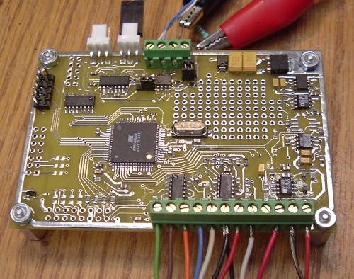
I
laid out an ExpressPCB mini-board (3.8" x 2.5") to provide one node for
the house,
one for the boat, and one extra (3 for $59 including shipping). It has
the CPU and support stuff plus analog circuitry to interface with the
sensors. This is my first SMT home project.
Wind Speed
The
Maximum Instruments wind speed sensor is a three cup anemometer. It's
output is an AC sine waveform whose amplitude and frequency both
vary linearly with wind speed. The frequency is hard to measure at low
speeds since the amplitude is also low. So I measure the amplitude by
converting the AC to DC and
then using an A/D channel to convert to digital. The AC-DC circuit is a
textbook precision full-wave rectifier with filter made from two
op-amps and two diodes. I'm going to need to investigate the
sensor gain to get the wind speed readings to be accurate. But for now
I just guessed
at the scaling and it seems close. The sensors are pretty accurate and
should provide about 5% accuracy. The circuit is about 3%
accurate using 1% resistors.
Wind Direction
To interface to a CPU isn't quite as simple. It requires a dual polarity (AC) drive to the common wire and sensing current in both directions in the other four wires. I use a CMOS inverter to apply either +5V or GND thru a 470 ohm resistor for the drive. For the sense I use another inverter driving 4 2.2K resistors which act as either pull-up or pull-down resistors. An LM339 quad comparator detects the current direction by sensing whether these wires are > or < 2.5V. The measurement is done in two phases: first see which of the wires conducts in the positive direction, then in the negative. Assemble these two four bit values into one eight bit byte, and then look up all 16 possible values to determine which of 16 directions it is.
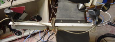
This sensor is not balanced and so needs to be installed perfectly level. That and the fact that it only resolves to 16 directions make it unsuitable for use on a boat. The sensors are to be mounted on a TV antenna mast on the roof my house.
House Power
The current waveforms of motors, heaters, incandescent lights, etc. are generally sinusoidal, but electronics typically draw current only during the AC voltage peaks, making the current waveform of a whole house a pretty complex waveform. So a proper RMS-DC converter is needed. I use the Analog Devices AD736 which conveniently accepts a low level signal directly from the current probe: 1mV/A. So 100A of house current = 100mVDC. I gain this up by x20 (actually x21) using a precision op-amp. Precision because 1mV of offset error is 1A of AC error.
The A/D on the Mega128 uses an external 4.096V precision reference (REF3040) which along with the 10 bit A/D gives 4.00mV / LSB. Since the X20 op-amp outputs 20mV/A, the final A/D resolution is 5LSB / A or 200mA RMS. Good enough for a whole house. I estimate the gain error at about 3%. I could use 0.1% resistors or a matched pair in the gain stage to make it better. There's also about a 0.6A unaccounted offset error in the op-amp that I need to track down.
Barometer
Pressure transducers that measure barometric pressure are readily available. I use a XXX. It's a bridge that can be driven from the 4.096V reference and outputs a differential signal of about 80mV at 15PSI. Barometric pressure varies from about 900mB in a hellacious storm to about 1050mB on a big Bermuda high. That's about 13-15PSI. So about 13/15 of the sensor's range is not needed.
The circuit consists of an Instrumentation Amplifier (IA). These parts generally are in an 8 pin package similar to a single op-amp, but with three extra pins: two to connect an external resistor to set the gain, and one for a reference connection, typically ground. They are low noise, low offset, precision. parts. I like the INA126 since it's cheap, but had an INA118 laying around. Since I want to maximize the A/D range I include a big + offset voltage from the 4.096V reference. This would typically drive the IAs output positive and further out of range, so I swap the two inputs to subtract the signal from the offset. I could have also used normal + polarity and a - reference, but this system doesn't have a - reference. Then fix all the gain and offset and polarity in software.
Gain is set by a 1K resistor to 1+(50K/R) = 51.0 80mV X 51 - 4.08V, and with a 4mV / LSB A/D the barometer will resolve 1/1000 of full scale or about 1milliBar.
There's a .1uF cap across the sensor to filter high frequencies out.
Microprocessor A/Ds
The A/D on most micros is generally pretty good, giving noise and linearity performance near the ideal 0.5LSB. I used the 68hc11's 8 bit A/D for years with success. Modern micros generally offer 10 bit A/Ds. With care in design the noise and linearity performance is good, but the internal reference voltage generally isn't very accurate. In fact in the MEGA128 it's pretty terrible at -6 / +9% accuracy. The reference directly affects gain measurement accuracy. There are couple of good ways to improve this.
Use the internal reference and calibrate it's gain against an external measurement. Then store the calibration factor in EEPROM. With this approach every unit needs to be calibrated and every measurement needs to be corrected. And multiplying a 10 bit A/D value increases INL because multiplying by a fractional number causes rounding errors. Also this technique requires a calibration step and software. Using the Vcc supply may be a bit more accurate. Most three terminal fixed voltage regulators are about +/- 5%. Another gotcha of this approach is that the A/D can only measure up to its reference, so if the reference is -5% worst case, you can't depend on having the top 5% of the A/D codes (5% of 1024 = 51 codes) available.
the '4' in REF3040 stands for 4.096V. Other voltages are available in this series. With a reference, you are paying for accuracy and drift.
Why 4.096V? I run The MEGA128 power at +5V and the higher the reference, the better the A/D performance in terms of noise and linearity. But it's hard to build a precision reference at 5.00 V when the supply is 5V. Also 4.096 / 1024LSBs = 4.00mV /LSB which can make the scaling math a bit easier. If you have low amplitude sensors you're generally better off amplifying them in a separate, nice clean amplifier than trying to get your sensitivity by operating the A/D from a lower reference. Besides, most A/Ds are specified for about a 2V minimum reference to achieve their accuracy specs.
For bipolar (+/-) sensors you may need to bias the output of the sensor at 1/2 of the reference voltage. I sometimes use a precision divider with matched or 0.1% resistors and buffered by a decent op-amp to generate the Ref/2 voltage. I use this on the Boat sensor board. If you need a - reference also, a matched pair of resistors and an inverting op-amp will do it.
Averaging
Fast A/Ds like those found in micros are great, but they are sampling A/Ds that tend to have fast input buffers and a sample and hold (S/H). This means that if a signal has noise or high frequency stuff, and the noise reaches a peak at the exact measurement time, then the noise affects that measurement. To make matters worse, if there is a frequency component and your sampling isn't >=2X the highest frequency, then you get aliasing which causes these high frequency errors to appear as DC errors. The best solution is filtering and averaging. That A/D is just sitting there not doing anything most of the time. Use it to sample the signal faster, then digitally average the results. Not only do you reduce noise and aliasing, but you can even squeeze a bit more out of your A/D.
But before averaging, limit the bandwidth of your input signal to what you really need. A simple RC filter may work. If you're measuring DC signals only once per second, then having signal bandwidth above 0.5Hz can only cause aliasing. And mixed digital / analog designs tend to pick up noise on the analog signals. Or maybe there's RFI on the wires. Or noise from any where. Filtering improves A/D noise performance. After that you're still stuck with a just a 10 bit A/D, right? How about those nice averaging A/Ds like dual slope, Sigma-Delta, etc? They get much more resolution and lower noise? You can improve signal to noise ratio (SNR) and resolution if you emulate some of this averaging by taking multiple measurements and averaging the results digitally. The theoretical best improvement in SNR is sqrt(n). So if you average 16 measurements, you get a 4X improvement in SNR. What you don't get is much better DC accuracy. This assumes that the noise you're trying to filter out occurs with a random distribution across those 16 readings.
Eliminating a specific noise frequency can also be done by averaging. The world is full of 50/60 Hz power line noise: 60Hz for US and Japan, 50Hz for most other countries. Your DMM provides nice stable readings in this noisy environment by averaging over a whole number of power line cycles and thus rejecting them. If you average one whole 60 Hz cycle (16.6mS) , the positive and negative half cycles cancel out, leaving 0 error. If your average is 1/2 of a 60Hz cycle (8.33mS) , then you may catch one entire positive or negative half cycle, depending on where you start in the cycle, and thus add or subtract a big error to your measured signal. The trick is to average over whole cycles. To eliminate both 50 and 60Hz, use an average time that is a multiple of both 1/60 (16.66mS) and 1/50 (20.0mS). 100ms is the fastest time: 6 60Hz or 5 50Hz cycles. Any integer multiple of 100mS is also fine.
With an A/D, measure every 1 mS or so and average the readings together. You can do a fancy DSP FIR filter or moving average, but simply accumulating the 10 bit A/D readings in a 32 bit integer will do the job with a lot less processor cycles: (accum += atodReading). At the end you need to scale the result. If you only want 10 bits resolution, divide the result by the number of samples you took. If it was a binary number of samples, just shift right. If you want to squeeze a bit more resolution in your result, just divide by a smaller number. I have used a 1mS interrupt to trigger the A/D measurements and do the integration and average counting right in the interrupt routine. When it has accumulated a full average, it sets a flag so the main routine can get the value and process it.